
All About Die Cutting?
Die cutting sounds simple until it steals your timeline. A gasket lifts, a foam pad shrinks, or an adhesive frame traps bubbles. Now your “tiny part” becomes a line-stopper. That’s the pain: rework, cosmetic rejects, missed ship dates, and a sourcing team stuck juggling suppliers instead of shipping product.
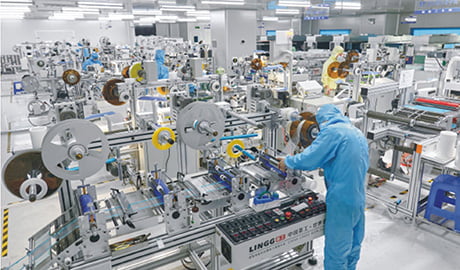
Die cutting is a precision converting process that turns rolls or sheets—foam, film, non-woven, rubber, and adhesive tapes—into repeatable parts for sealing, bonding, insulation, damping, and protection. In modern manufacturing, the value isn’t “cutting.” It’s consistency: stable geometry, clean edges, controlled adhesive behavior, and delivery formats that apply fast on the line. Define your stack-up, CTQs, and application method early, and you prevent most late-stage surprises.
If you’re an OEM buyer, you don’t want a textbook. You want a path. What to specify. What to test. What to ask before committing to volume.
I’ll break die cutting down like a factory person who also runs BeeChair in my imagination: I love comfort, and nothing is less comfortable than “random failures” that aren’t random.
What does die cutting actually produce for OEMs?
We produce functional parts that sit between “design” and “assembly.”
Seals and gaskets.
Insulation pads.
Anti-rattle pieces.
Protection films.
Bonding layers.
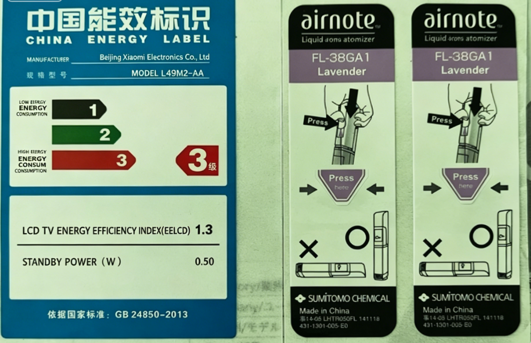
Label constructions that must scan and stay flat.
These parts prevent dust, noise, water, heat, and vibration from becoming warranty problems.
The customer pain is scale.
A sample can look perfect once.
Mass production needs repeatability.
When an edge lifts by 0.5 mm, you may not notice on the bench.
Your customer notices after shipping.
And your line notices immediately.
That’s why we treat die-cut parts like engineering components, not “stickers.”
Which die cutting process should you choose: rotary, flatbed, or digital?
Rotary die cutting is roll-to-roll and continuous.
It’s built for stable volume.
It holds pitch well for peel-and-place and automation.
It’s great for thin films, label stocks, foils, and adhesive constructions that strip waste cleanly.
Flatbed die cutting uses a press stroke.
It’s often calmer for thicker foams, rubber sheets, and heavier laminates.
It can handle larger parts and tricky geometries with less web stretch risk.
Digital cutting is useful for early iteration.
But it can mislead you if you validate only digitally.
Soft foams stretch.
Adhesives behave differently at speed.
Waste removal behaves differently at speed.
My rule is simple.
Prototype fast.
Qualify with the same process you will run in production.
Otherwise you approve a sample your factory can’t repeat.
What materials and adhesive stack-ups cause the most trouble?
Most trouble starts in materials, not machines.
Foam density changes compression.
Film thickness affects stiffness and curl.
Rubber rebound affects sealing.
Adhesive chemistry affects tack, peel, shear, and aging.
If the material is wrong, the cut line can be perfect and the part still fails.
The biggest hidden headache is adhesion variability.
Surface energy, temperature, contamination, and dwell time change wet-out.
“It sticks today” does not mean “it sticks after eight weeks in heat.”
Bubbles, edge lift, and residue usually come from stack-up decisions and lamination settings.
Here are the most common pain patterns we see:
- Edge lift after 24–72 hours (stress + shrink + insufficient bonding land)
- Bubbles after shipping (dust + trapped air + poor wet-out)
- Residue during rework (removability never defined, heat aging)
- Dimensional drift across lots (material batch variation, tension control, tool wear)
When you tell us when the failure appears, we can solve faster.
What’s the difference between kiss-cut and through-cut?
This decides how your part arrives to the line.
Kiss-cut means we cut the face material but leave the liner intact.
Parts stay registered.
Parts stay clean.
Peel-and-place stays fast.
Through-cut means we cut through the entire stack.
You get loose pieces.
Loose pieces can be right for some non-adhesive parts.
But they create handling pain:
- dust pickup
- bending
- counting errors
- mixed orientation
- slower placement
Cut depth matters more than buyers expect.
Too deep and the liner is scored.
Then liners tear during peel.
Operators slow down.
Corners bend.
Adhesive gets contaminated.
Too shallow and parts won’t release.
Operators pick edges.
Thin frames stretch.
Placement becomes inconsistent.
A “good” part is not just the right shape.
It’s a shape that peels cleanly and places fast at shift speed.
What CTQs and inspections should you define before you approve a supplier?
Start with CTQs.
Critical-to-quality features.
For die-cut parts, CTQs often include:
- sealing width and contact land
- hole position and window alignment
- outline and corner radii
- thickness (especially installed thickness under compression)
- critical edges (cosmetic and functional)
Then align measurement method.
If you don’t agree on how to measure, “in spec” becomes an argument.
We also recommend defining:
- sampling rules (where on the roll, how many pieces)
- orientation and peel direction requirements
- roll rules if you use applicators (pitch, core, unwind direction, splice rules)
Ask for capability behavior, not a pretty sample bag.
A stable process beats a one-off miracle.
What validation steps prevent painful surprises at launch?
If you only test “looks good now,” you validate hope.
We validate behavior over time.
For adhesive parts:
- peel stability after dwell time
- shear resistance at operating temperature
- edge lift risk at corners after heat exposure
- residue behavior if rework/service is expected
For foam and sealing parts:
- compression behavior in the real assembly
- compression set risk if the product cycles
- leak path risk from gaps and tolerance stack
For all parts:
- placement time on the real station
- bubble rate and cosmetic yield
- packaging protection against friction and vibration
- cleanliness and contamination control
A practical qualification path looks like this:
Screen (week 1)
Confirm material and process fit.
Confirm delivery format feasibility.
Confirm risks: waste stripping, web stretch, corner stress.
Prove (weeks 2–4)
Sample using the intended production method and intended format.
Not hand-cut mockups.
Not “close enough.”
Pilot (weeks 5–12)
Run a small lot under production-like conditions.
Track defect rate and rework minutes.
Check after 24–72 hours.
Then lock the spec and revision control.
If a part only works when applied “carefully,” it does not work.
Production is fast.
So the part must be easy.
Why do die-cut parts pass samples but fail in mass production?
Because variation shows up at scale: material batch differences, tool wear, adhesive aging, liner release drift, and handling effects. The fix is validating after time and stress, not only immediately.
What information should you send Sanken for a fast, accurate quote?
Cut line or drawing revision, stack-up and thickness targets, what it bonds to, the environment (heat/humidity/chemicals/UV), forecast volume, and how the part is applied (manual, jig, semi-auto, automation). A photo of the mating surface helps us spot edge-stress and gap risks.
Can you reduce rework and speed up placement without changing function?
Often yes. Format is a powerful lever. Tabs, liner selection, pitch control, and counted kits can reduce misplacement and rework without changing the part’s function.
How do you prevent bubbles, lifting, and residue?
We tune the system: adhesive behavior, surface cleanliness requirements, lamination window, corner geometry, and packaging protection. Then we validate after 24–72 hours and under real handling. Fixing it later costs more than designing it right.
Conclusion
Die cutting turns roll and sheet materials into precise, repeatable parts that protect yield and schedules. Define stack-up, CTQs, tests, and delivery format early, and you avoid rework. If you share your drawing and use conditions, we’ll recommend a stable converting path that runs cleanly at volume.