Die cutting trial failures often happen before mass production begins, but they can still cost buyers time, tooling money, material waste, and delayed project schedules. For engineers, the real challenge is not only making one acceptable sample. The real challenge is proving that the part can be produced repeatedly, assembled smoothly, and perform reliably in the final product.
At Sanken, we often see trial failures caused by unclear drawings, unsuitable materials, unrealistic tolerances, weak adhesive selection, poor waste removal, and missing application details. The good news is that most of these failures can be reduced before tooling starts.
Why This Topic Matters for OEM Manufacturing
For OEM manufacturing, a die cutting trial is not just a sample-making step.
It is a risk-control stage.
A successful trial helps confirm whether the material, tooling, tolerance, adhesive structure, packaging method, and assembly process can support mass production.
A failed trial usually means more than one problem. It may reveal that the foam is too soft, the PET film stretches, the adhesive overflows, the hole position is unstable, or the part design is too narrow for clean waste removal.
For automotive electronics, medical devices, industrial enclosures, appliances, battery systems, and optical components, trial failure can delay product launch and increase supplier coordination cost.
That is why engineers should treat die cutting trials as an engineering validation process, not only a price-checking step.
Common Problems and Production Risks
Many die cutting trial failures are predictable.
The problem is that buyers and suppliers sometimes focus too quickly on price, shape, and lead time, while ignoring manufacturability.
| Trial Failure Problem | Common Cause | Production Risk |
|---|---|---|
| Rough cutting edges | Wrong tooling or cutting pressure | Poor sealing, dust, burrs |
| Hole position deviation | Weak tolerance planning | Assembly mismatch |
| Adhesive overflow | Soft adhesive or excessive pressure | Contamination and rejected parts |
| Foam deformation | Wrong density or compression load | Poor sealing or unstable fit |
| PET film stretching | Poor tension control | Dimensional drift |
| Waste removal failure | Complex shape or narrow features | Low yield and torn parts |
| Liner release problems | Wrong liner or kiss cutting depth | Slow assembly and damaged parts |
| Sample passes but batch fails | No production repeatability check | Mass production instability |
Engineers can reduce these risks by reviewing the full part structure before the first die cutting trial.
A drawing shows the target shape.
It does not always show how the material will behave under cutting pressure, lamination tension, peeling, compression, or assembly.
What Buyers or Engineers Should Check First
Before ordering a die cutting trial, engineers should prepare the information that affects real production performance.
This does not need to be complicated.
But it must be complete.
| Checklist Item | What to Confirm | Why It Matters |
|---|---|---|
| Application | Sealing, bonding, insulation, cushioning, shielding | Defines material and process direction |
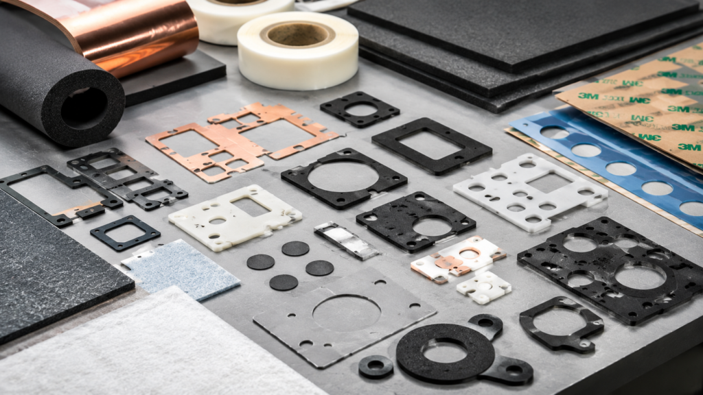
| Material type | Foam, rubber, PET, adhesive tape, felt, silicone | Controls cutting behavior and performance |
| Thickness | Nominal thickness and tolerance | Affects compression and assembly fit |
| Critical dimensions | Holes, edges, sealing walls, inner openings | Prevents functional failure |
| Adhesive need | Adhesive type, liner, bonding surface | Prevents lifting, shifting, peeling |
| Tolerance | Critical vs non-critical dimensions | Controls cost and manufacturability |
| Assembly method | Manual, fixture, automated, screw compression | Affects part handling and design |
| Testing needs | Aging, peel, compression, sealing, insulation | Confirms real performance |
| Packaging | Roll, sheet, liner, orientation, protection | Prevents deformation and assembly delay |
The most important point is this: not every dimension needs the tightest tolerance.
Engineers should identify which dimensions affect function.
A screw hole may need tight control.
A sealing wall may need tight control.
A non-contact outer edge may allow more flexibility.
This approach improves production stability without adding unnecessary cost.
Material and Process Considerations
Material behavior is one of the biggest reasons die cutting trials fail.
Foam compresses.
Rubber rebounds.
PET film stretches.
Non-woven felt can release fibers.
Adhesive tape may flow at the edge.
Silicone may deform and create bonding challenges.
Conductive materials may require clean edges and accurate alignment.
That is why engineers should never choose material only by thickness or price.
The material must match the final application.
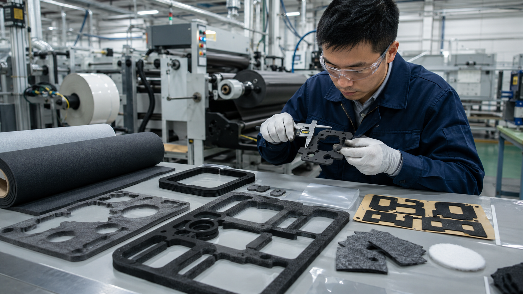
For foam gaskets, engineers should review compression ratio, rebound, density, and sealing width.
For adhesive-backed parts, they should review bonding surface, adhesive type, liner release, and kiss cutting depth.
For PET insulation films, they should review dimensional stability, static control, edge cleanliness, and handling method.
For non-woven felt parts, they should review fiber shedding, thickness variation, acoustic performance, and cutting edge condition.
Process selection also matters.
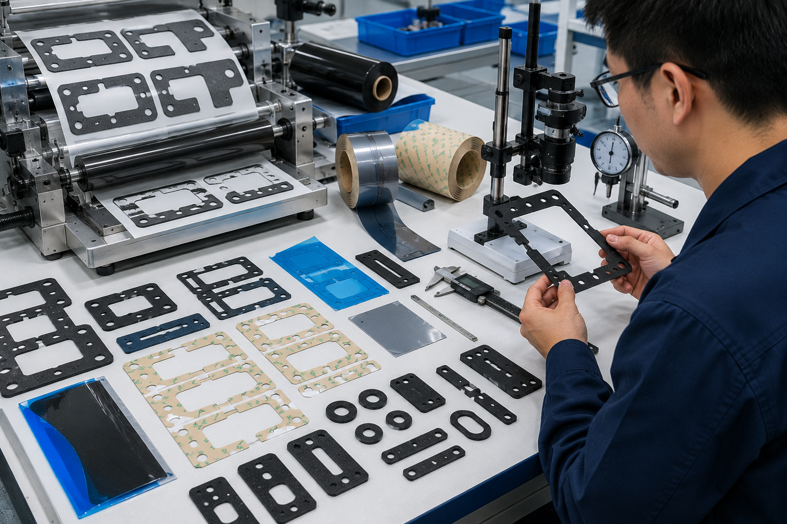
Flatbed die cutting may work better for thicker foam, rubber, or low-volume trials.
Rotary die cutting may be better for roll materials, adhesive tapes, films, and high-volume production.
Kiss cutting is often required for adhesive-backed materials where the top layer must be cut without damaging the release liner.
If the wrong process is selected, the first sample may already carry hidden production risks.
How Engineers Can Reduce Trial Failures
The best way to reduce die cutting trial failures is to make the trial more informed before it begins.
Engineers should review the part from five angles.
First, check the function.
What must this part do in the final product?
A sealing gasket, insulation film, adhesive spacer, and acoustic felt pad all need different design logic.
Second, check the material.
Can the selected material hold the required shape, tolerance, thickness, compression, and adhesive structure?
Third, check the geometry.
Complex shapes, narrow bridges, small holes, sharp corners, and short hole-to-edge distances increase trial risk.
Fourth, check the process.
The supplier should confirm tooling type, cutting method, lamination method, waste removal plan, and inspection method before trial production.
Fifth, check the validation plan.
A trial should not only answer, “Can this part be cut?”
It should answer, “Can this part be produced, handled, assembled, and used reliably?”
For B2B buyers, this is where a professional supplier creates value.
A basic supplier may make a sample.
A real manufacturing partner helps reduce the number of failed trials.
Why Trial Failures Often Happen After the First Sample
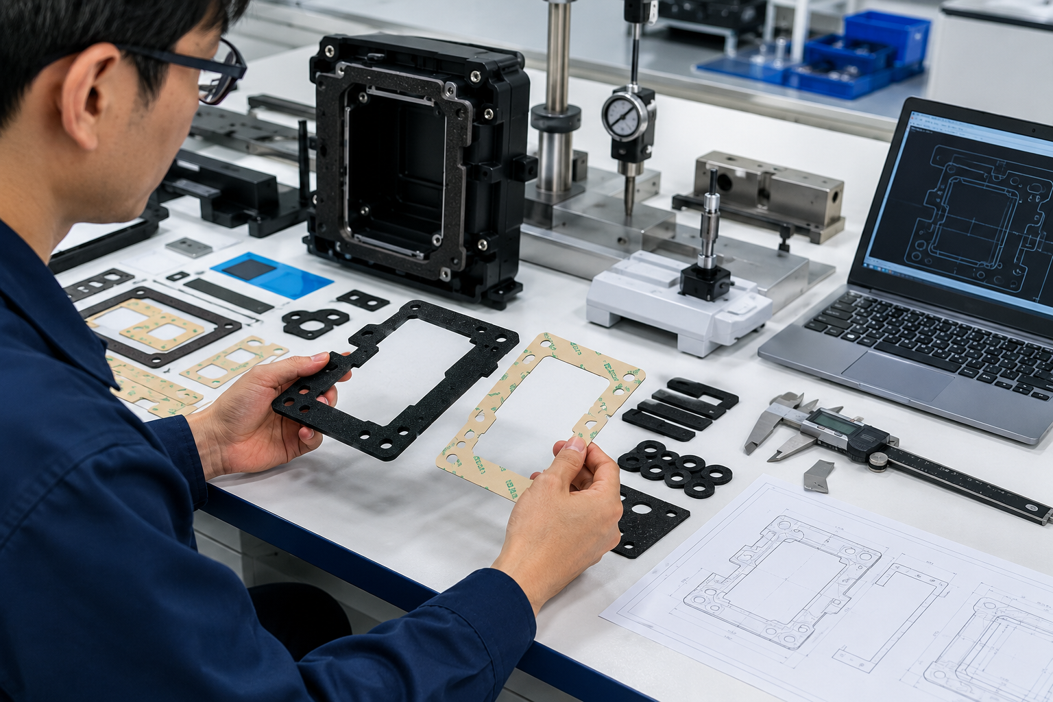
One common mistake is approving the first sample too quickly.
A first sample may look good because it was made slowly, manually adjusted, and inspected carefully.
Mass production is different.
Production introduces tool wear, material batch variation, roll tension changes, adhesive behavior changes, operator differences, and longer machine running time.
That is why engineers should ask for more than a nice-looking sample.
They should ask:
- Can the supplier repeat the result?
- Are the critical dimensions stable?
- Can waste be removed cleanly?
- Does the adhesive stay within the edge?
- Does the liner peel smoothly?
- Does the part fit the real assembly?
- Does the packaging protect the part?
If these questions are answered early, the trial process becomes much more useful.
How Sanken Helps Reduce Risk Before Mass Production
At Sanken, we help OEM customers reduce die cutting trial failures by reviewing the project before tooling and sampling.
For custom die cut parts, we focus on the details that usually cause problems: material behavior, adhesive structure, tolerance risk, hole position, minimum width, waste removal, compression, liner release, and packaging.
For foam gasket projects, we check sealing path, thickness, compression range, and assembly pressure.
For adhesive tape parts, we check bonding surface, adhesive type, kiss cutting depth, liner stability, and overflow risk.
For PET insulation films and electronic components, we check dimensional stability, cleanliness, edge quality, and assembly fit.
For non-woven felt and acoustic parts, we check thickness, fiber condition, cutting edge, and application environment.
Our goal is not only to help customers get a sample.
Our goal is to help customers reach stable mass production with fewer trial failures, fewer tooling changes, and less wasted time.
That is why we work closely with OEM engineers and buyers from drawing review to sample validation and production planning.
FAQ
What is the most common reason for die cutting trial failure?
The most common reason is incomplete engineering review before sampling. The drawing may show the shape, but it may not fully explain material behavior, adhesive needs, assembly force, tolerance priorities, or testing requirements.
How many die cutting trials are normally needed?
Simple parts may need one trial. Complex parts with adhesive, tight tolerances, narrow features, or multilayer materials may need two or more trials. The number depends on material difficulty, tooling complexity, and validation requirements.
Can better drawings reduce trial failures?
Yes. Clear drawings reduce misunderstanding. Engineers should mark critical dimensions, tolerance requirements, material specifications, adhesive areas, hole positions, and application notes.
Why do adhesive-backed parts fail during trials?
Adhesive-backed parts may fail because of adhesive overflow, wrong liner selection, unstable kiss cutting depth, weak lamination, difficult peeling, or poor bonding surface compatibility.
Why do foam parts deform during die cutting trials?
Foam can deform because of low density, excessive cutting pressure, narrow wall design, unstable thickness, or difficult waste removal. Foam type and compression behavior should be reviewed before tooling.
Should engineers test samples in the real assembly?
Yes. A sample should be tested in the real housing or assembly environment whenever possible. Fit, compression, peel, sealing, insulation, and handling should be checked before mass production.
How can buyers reduce unnecessary tooling cost?
Buyers can reduce tooling cost by reviewing material, tolerance, part geometry, adhesive structure, and critical dimensions before cutting the tool. Early design adjustment is usually cheaper than repeated tooling correction.
Conclusion
Engineers can reduce die cutting trial failures by checking material behavior, critical tolerances, adhesive structure, tooling method, waste removal, assembly fit, and validation requirements before sampling. At Sanken, we help OEM buyers and engineers identify these risks early, so custom die cut parts can move from trial to mass production with fewer delays, lower cost, and more stable quality.