
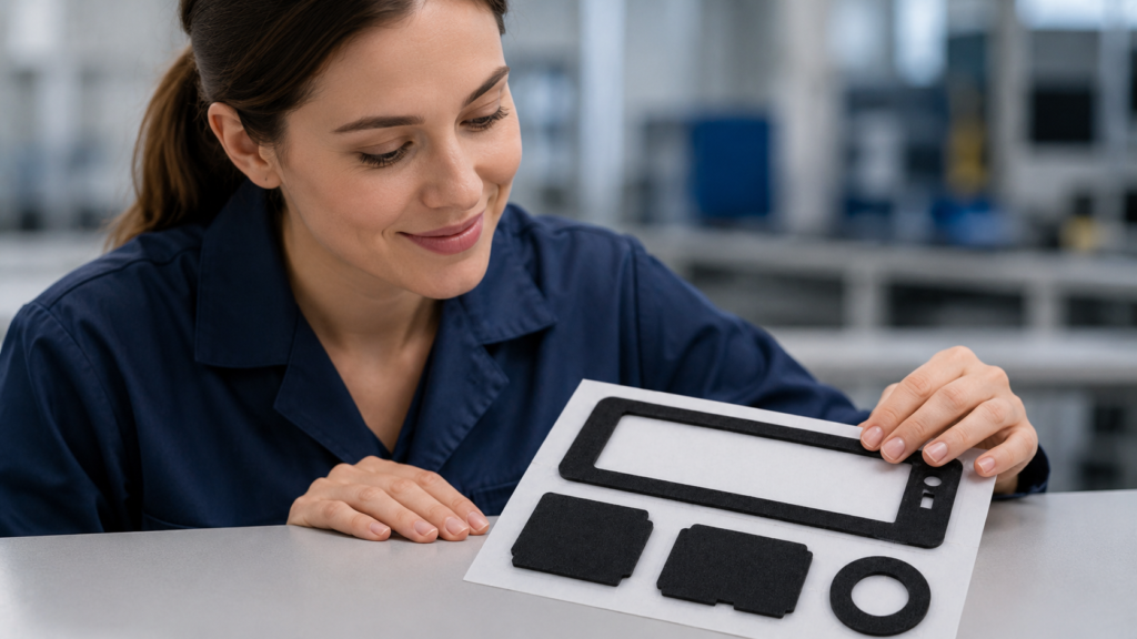
Foam board can be cut into simple shapes with a sharp craft knife, a stable cutting mat and a paper template. This method is practical for signs, display models, packaging mockups and early design prototypes.
However, a hand-cut prototype does not represent the consistency of a production component. When a project requires repeated dimensions, narrow walls, internal holes, adhesive backing or controlled delivery on a release liner, professional precision die cutting is usually the more reliable method.
It is also important to distinguish paper-faced foam board from industrial foam materials. They may look similar, but they serve different purposes and require different material-selection and converting methods.
Can Foam Board Be Cut by Hand?
Yes. Ordinary paper-faced foam board can be cut by hand when only a few simple shapes are required.
The basic tools include:
- A sharp craft or utility knife
- A stable cutting mat
- A printed paper template
- Low-tack tape
- A straightedge for straight cuts
Place the board flat on the cutting mat and secure the template without damaging the paper surface. Make a light first pass to establish the cutting path, then deepen the cut gradually.
Several controlled passes normally produce a cleaner edge than attempting to cut through the entire board in one movement. The knife should remain vertical to reduce angled edges and uneven dimensions.
For circles and curves, rotate the board gradually while following the template. Do not pull the shape from the sheet until the surface, foam core and back layer have been completely cut.
This method is sufficient for:
- Visual models
- Display boards
- Signs
- Packaging mockups
- Early fit-check samples
- One-off shapes without tight tolerances
Detailed hand-cutting instructions are less useful once a project moves toward repeated production. At that stage, the material structure, dimensional requirements and assembly method become more important than the cutting technique itself.
Why Hand Cutting Is Mainly Suitable for Prototypes
Hand cutting depends heavily on the operator, blade condition and cutting direction. Even when the first sample looks acceptable, it may be difficult to reproduce the same result across dozens or thousands of parts.
Common limitations include:
| Hand-cutting problem | Production impact |
|---|---|
| Angled edges | The top and bottom dimensions may be different |
| Foam compression | Part thickness or edge shape may become inconsistent |
| Cuts extending beyond corners | Narrow frames may tear or lose effective bonding area |
| Rough internal openings | The part may interfere with another component |
| Variation between parts | Assembly position and coverage may change |
| Surface-layer separation | The part may lose strength or appearance quality |
| Manual adhesive application | Adhesive position and exposed edges may vary |
For an early prototype, these variations may be acceptable if the objective is only to confirm the approximate size or shape.
For an OEM component, the same variations can affect sealing, cushioning, spacing, insulation or assembly alignment. A prototype should therefore be treated as a design reference—not as proof that the part is ready for production.
Foam Board and Industrial Foam Are Not the Same
The term “foam board” usually refers to a lightweight foam core laminated between paper or plastic surface layers. It is primarily intended for displays, signs and models.
Industrial foam parts may use materials such as:
- PE foam
- EVA foam
- PU foam
- EPDM foam
- Silicone foam
- Rubber foam
These materials may be converted into custom die-cut parts for sealing, cushioning, spacing, vibration reduction or assembly support.
| Requirement | Paper-faced foam board | Industrial foam |
|---|---|---|
| Main application | Displays, signs and models | Sealing, cushioning and functional components |
| Material structure | Foam core with surface facings | Open-cell or closed-cell foam |
| Dimensional control | Usually moderate | Defined by the drawing and assembly |
| Compression performance | Normally not a primary requirement | Often an important selection factor |
| Adhesive backing | Uncommon | Frequently required |
| Environmental validation | Limited | May include temperature, humidity and aging |
| Delivery format | Individual shapes | Parts, sheets, rolls or kits |
Paper-faced foam board should not be selected for an industrial gasket simply because its thickness appears suitable. Industrial foam selection should consider density, cell structure, compression behaviour, recovery, temperature exposure and compatibility with the bonding surface.
When Should Professional Foam Die Cutting Be Used?
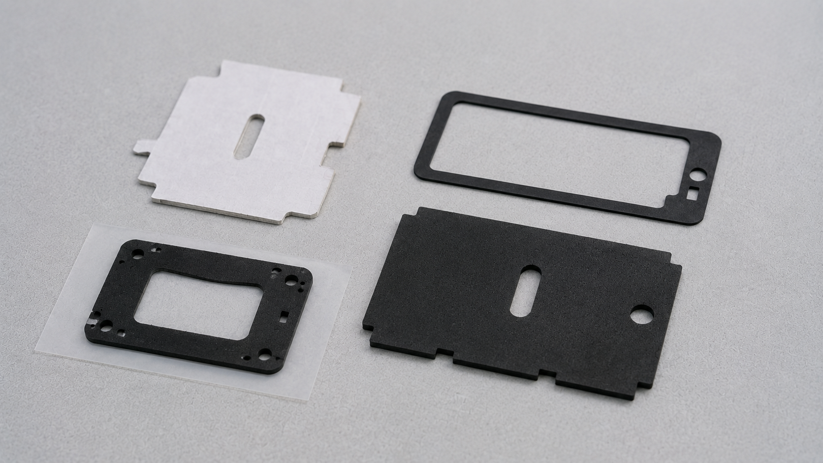
Professional foam die cutting becomes appropriate when a project requires:
- Repeated dimensions
- Narrow frames or walls
- Multiple holes or complex profiles
- Consistent edge quality
- Adhesive lamination
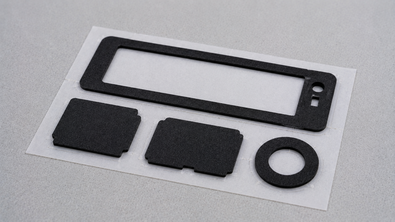
- Kiss cutting onto a release liner
- Waste-matrix removal
- Sheet or roll presentation
- Higher production quantities
- Defined inspection requirements
A professional cutting process can produce foam gaskets, mounting pads, strips, spacers, cushioning parts and adhesive-backed frames.
For foam gaskets and sealing components, the objective is not only to cut the external shape. The part must also match the actual gap, compression requirement, bonding surface and assembly condition.
What Changes When Adhesive Is Added?
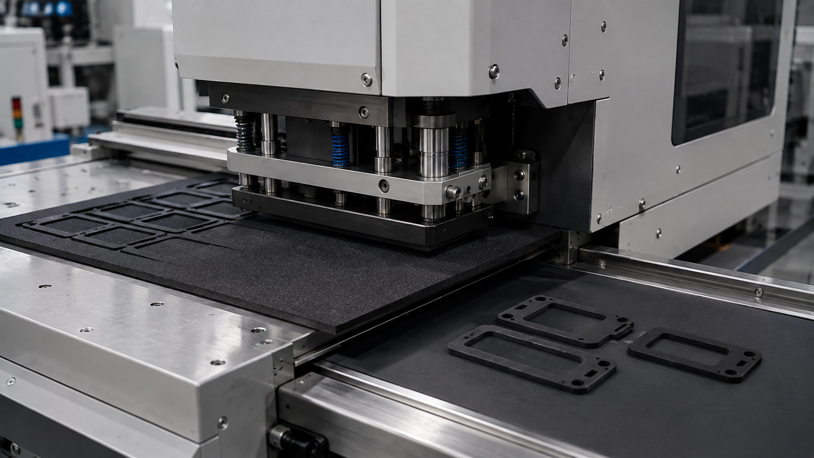
An adhesive-backed foam part is a multilayer construction rather than a simple foam shape. It may contain:
- A foam layer
- A pressure-sensitive adhesive
- A release liner
The converting process must control all three layers.
Important factors include:
- Adhesive compatibility with the foam
- Bonding performance on the customer’s substrate
- Adhesive position and setback
- Liner release force
- Cutting depth
- Edge adhesive flow
- Waste-removal direction
- Part spacing on the liner
For kiss-cut parts, the cutting tool should pass through the foam and adhesive construction without cutting through the release liner.
If the cut is too shallow, the finished part may remain connected to the waste material. If the cut is too deep, the liner may become weak or tear during peeling and assembly.
More information about multilayer risks is available in Adhesive-Backed Die-Cut Components: Materials, Risks and OEM Assembly Tips.
Why Part Geometry Matters
Some foam shapes are more difficult to manufacture than they appear on a drawing.
Examples include:
- Very narrow gasket walls
- Small internal holes
- Closely spaced parts
- Sharp internal corners
- Long thin strips
- Large frames with limited support
- Multiple disconnected sections
A narrow frame can stretch or lift during waste removal. Small internal waste sections may remain inside the opening. Long strips may deform when removed from the liner.
The drawing should therefore be reviewed together with:
- Foam thickness
- Material density
- Compression behaviour
- Minimum wall width
- Hole dimensions
- Corner geometry
- Adhesive construction
- Liner type
- Part spacing
- Delivery format
The objective is to maintain both the required function and a stable converting process.
What Should Be Confirmed Before Production?
Before converting a hand-cut foam concept into a production part, the buyer and manufacturer should confirm:
- Part drawing and critical dimensions
- Intended function
- Foam material and thickness
- Density or compression requirement
- Open-cell or closed-cell structure
- Permanent or removable adhesive
- First and second bonding substrates
- Release-liner requirement
- Sheet, roll or individual-part delivery
- Assembly and peeling method
- Operating temperature
- Humidity or chemical exposure
- Prototype quantity
- Expected annual volume
- Inspection requirements
The actual substrates should be provided for bonding evaluation whenever possible. Foam color and thickness alone cannot confirm that the material will perform correctly in the final assembly.
Prototype validation may include:
- Dimensional inspection
- Assembly fit
- Liner-peeling evaluation
- Adhesion testing
- Compression testing
- Environmental aging
- Packaging and handling checks
Results from these checks can be used to adjust the foam, adhesive, liner or geometry before production tooling is finalized.
How Sanken Converts Industrial Foam Parts
At Sanken, we convert industrial foam sheets and rolls into custom components for automotive, electronics, appliances, optical products and other OEM assemblies.
Depending on the drawing and material construction, our support can include:
- Foam and adhesive lamination
- Precision die cutting
- Kiss cutting
- Narrow foam frames and pads
- Release-liner configuration
- Waste-matrix removal
- Prototype sampling
- Dimensional inspection
- Sheet, roll and individual-part delivery
Sanken reviews the material, geometry, adhesive structure and assembly method together. This helps determine whether the part should be delivered as an individual component, retained on a sheet or arranged on a roll.
The delivery format should be confirmed early because it can affect part spacing, liner selection, peeling direction, packaging and assembly efficiency. Buyers can compare the available options in Die-Cut Parts in Sheets, Rolls, or Kits: How to Choose the Right Format.
Conclusion
Simple foam board shapes can be cut by hand for signs, models, packaging mockups and early design prototypes. A sharp knife, stable cutting mat, clear template and several light passes are normally sufficient for these purposes.
However, hand cutting becomes unsuitable when an industrial foam part requires repeated dimensions, narrow walls, internal holes, adhesive backing, controlled liner presentation or production-level consistency.
Moving from a hand-cut prototype to a professional die-cut component requires more than changing the cutting method. The foam structure, thickness, compression behaviour, adhesive, geometry, liner and delivery format must be evaluated as one system.
The final material and converted part should be validated under representative assembly and operating conditions before mass production.
Related Articles
- From Foam Rolls to Finished Parts: How Die Cutting Works
- Custom Die Cut Foam Gaskets: Automotive Electronics Design and Production Tips
- Die Cut Foam Gaskets: 7 Mistakes That Cause Poor Sealing
- Adhesive-Backed Die-Cut Components: Materials, Risks and OEM Assembly Tips
- Die-Cut Parts in Sheets, Rolls, or Kits: How to Choose the Right Format