
Which Custom Die-Cut Spacers Prevent Sensor Lens Offset During Assembly?
Sensor lens offset during assembly is usually not caused by one large mistake. It often comes from many small issues: uneven pressure, unstable spacer thickness, poor adhesive placement, material compression, dust, housing tolerance, or slight movement during bonding.
For camera modules, optical sensors, LiDAR units, medical imaging devices, automotive cameras, barcode scanners, and industrial vision systems, even a tiny offset can affect focus, image sharpness, light path alignment, sealing, and long-term reliability.
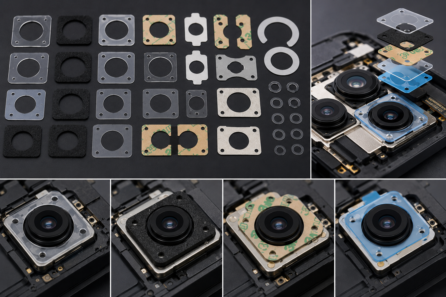
The best custom die-cut spacers for preventing sensor lens offset are dimensionally stable, low-compression, clean-edge spacers made from materials such as PET film, PC film, high-density foam, TPU film, adhesive-backed spacer films, or multilayer composite structures.
But the right answer depends on the assembly problem.
A spacer that works for a large automotive camera may not work for a miniature phone camera module. A soft foam spacer may absorb vibration well but may compress too much. A hard PET spacer may control height well but may not absorb shock. A double-sided adhesive spacer may improve assembly speed but may create offset if the adhesive flows unevenly.
For OEM buyers and engineers, the real question is not only “Which spacer material should I use?” The better question is: “Which spacer structure can control lens position, maintain thickness, bond reliably, and avoid shifting during assembly and aging?”
Why Sensor Lens Offset Happens
Lens offset means the optical lens, sensor, housing, or spacer does not stay in the correct position during or after assembly.
This may happen during:
- Manual placement
- Automated pick-and-place
- Adhesive bonding
- Screw fastening
- Heat curing
- Compression loading
- Vibration testing
- Aging tests
- Final product operation
Common causes include:
| Offset Cause | What Happens in Assembly |
|---|---|
| Spacer thickness variation | Lens height becomes inconsistent |
| Foam compression | Spacer collapses and lens shifts |
| Adhesive flow | Bonding layer becomes uneven |
| Poor die-cut tolerance | Spacer does not match housing geometry |
| Edge burrs or particles | Parts do not sit flat |
| Material shrinkage | Spacer changes size after heat or aging |
| Weak liner release | Adhesive part stretches during peeling |
| Housing tolerance stack-up | Small errors accumulate across layers |
The spacer is often a small part, but it controls a critical optical relationship.
If it fails, the customer may see blurry images, focus variation, sensor calibration failure, light leakage, or high inspection rejection.
What a Good Sensor Lens Spacer Must Do
A custom die-cut spacer for sensor lens assembly should not only separate two parts.
It should control position.
A good spacer should provide:
- Stable thickness
- Clean edges
- Low particle generation
- Accurate inner and outer dimensions
- Reliable adhesive bonding if needed
- Controlled compression
- Good flatness
- Low shrinkage
- Low outgassing
- Compatibility with optical assembly conditions
For optical modules, cleanliness and dimensional consistency are often more important than the spacer’s basic material cost.
A cheaper spacer may save a few cents but cause much higher losses if camera modules fail final inspection.
PET Film Spacers: Best for Stable Height Control
PET film spacers are often a strong choice when the main requirement is dimensional stability.
PET film offers:
- Stable thickness
- Good flatness
- Clean die-cut edges
- Low compression
- Good compatibility with adhesive lamination
- Strong dimensional control
PET spacers are suitable for:
- Camera module spacing
- Sensor insulation
- Display module support
- Optical film assemblies
- Electronic component positioning
When lens offset is caused by height variation, PET film is often better than soft foam because it does not compress easily.
However, PET has limited cushioning. If the assembly also needs vibration damping or shock absorption, PET may need to be combined with foam, adhesive, or elastomer layers.
PC Film Spacers: Good for Strength and Impact Resistance
PC film spacers are useful when the application needs more impact resistance or structural support.
PC film can provide:
- Good toughness
- Stable geometry
- Higher impact resistance than many films
- Reliable support in thin structures
PC spacers may be suitable for automotive cameras, industrial sensors, and protective optical assemblies where the spacer must hold its shape under stress.
The trade-off is that PC may not be as easy to process as standard PET in every structure, and cost may be higher depending on grade and thickness.
High-Density Foam Spacers: Useful When Offset Comes From Vibration
High-density foam spacers can help when the sensor lens needs both positioning and vibration control.
Foam spacers may be used to:
- Reduce rattling
- Absorb vibration
- Prevent hard contact
- Fill small gaps
- Protect lens housing surfaces
- Support shock resistance
But foam must be selected carefully.
Low-density foam may compress too much and cause lens movement. For sensor lens assemblies, the foam should usually have:
- Controlled density
- Low compression set
- Stable thickness tolerance
- Clean die-cut behavior
- Suitable hardness
- Good aging resistance
A foam spacer that feels soft and protective at first may become a problem if it flattens after long-term compression.
For precision optical assemblies, medium-to-high-density EVA foam, PE foam, or specialty foam structures are often more reliable than very soft low-density foam.
Adhesive-Backed Spacers: Good for Fast Assembly, Risky if Poorly Designed
Adhesive-backed spacers are common because they make assembly easier.
Workers or automated equipment can peel, place, and bond the spacer directly.
They are useful for:
- Camera module assembly
- Sensor housing bonding
- Display support
- Protective film placement
- Electronic component positioning
However, adhesive-backed spacers can create offset if the adhesive is not controlled.
Possible problems include:
- Adhesive thickness variation
- Edge lifting
- Adhesive overflow
- Uneven wet-out
- Liner release stretch
- Part distortion during peeling
- Position shift during bonding
For sensor lens applications, adhesive must not be treated as an afterthought.
The full structure matters:
film or foam spacer + adhesive layer + release liner + bonding surface + assembly pressure
If any layer behaves poorly, the lens position may shift.
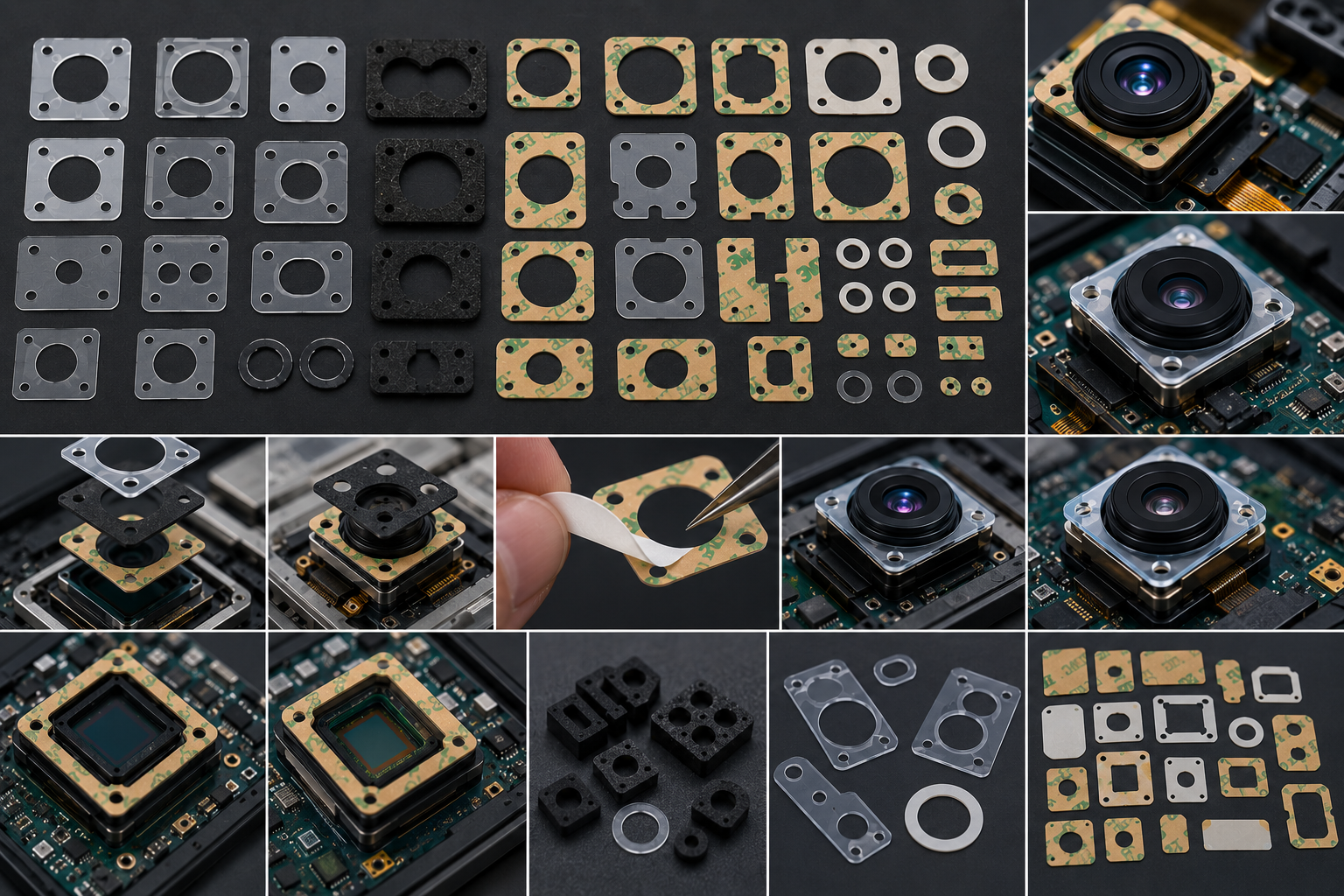
Multilayer Composite Spacers: Best When One Material Cannot Solve Everything
Some sensor assemblies need multiple functions at the same time.
For example:
- Stable height control
- Vibration damping
- Adhesive mounting
- Light blocking
- Dust sealing
- Surface protection
- Electrical insulation
In these cases, a single material may not be enough.
Common composite spacer structures include:
| Spacer Structure | Main Purpose |
|---|---|
| PET + adhesive | Stable height and easy bonding |
| PET + foam | Thickness control with cushioning |
| Foam + adhesive | Gap filling and quick assembly |
| PET + black film | Spacing and light blocking |
| TPU + adhesive | Flexible support for curved or soft assemblies |
| Foam + film + adhesive | Cushioning, stability, and bonding |
| Non-woven + film | Dust control and surface protection |
A composite spacer can be more effective than a single layer, but it requires better converting control. Layer alignment, adhesive lamination, total thickness, waste stripping, and liner release must all be stable.
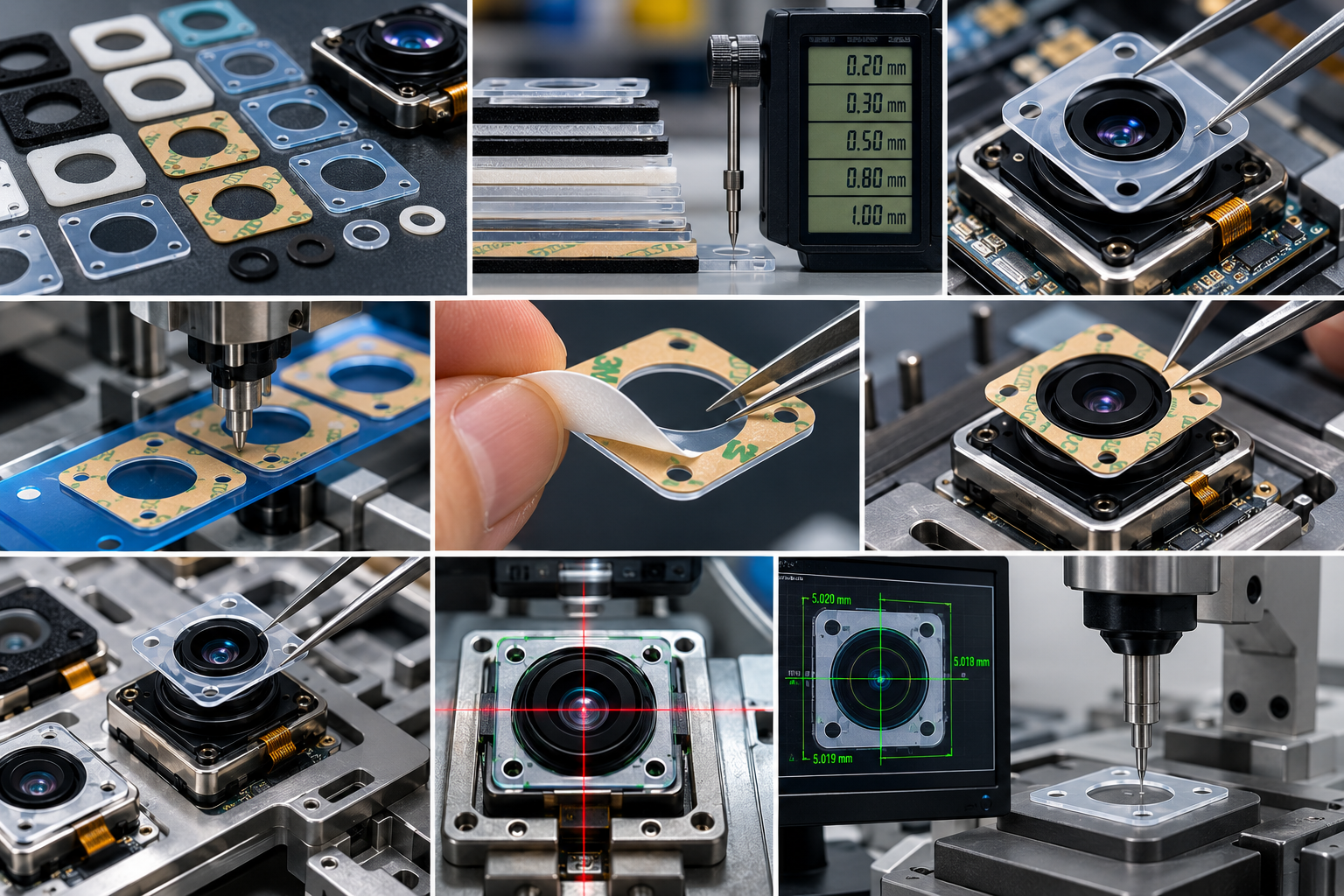
Thickness Tolerance Is the First Control Point
For sensor lens alignment, thickness tolerance is often the most important specification.
If the spacer is too thick, it may push the lens or sensor out of position.
If it is too thin, it may fail to support the module.
If thickness varies across the part, the lens may tilt.
Buyers should review:
- Nominal thickness
- Thickness tolerance
- Total stack-up tolerance
- Compression under assembly pressure
- Thickness after aging
- Thickness after adhesive lamination
Do not evaluate only the raw material thickness.
For adhesive-backed spacers, the total thickness includes the base material and adhesive layer. If a release liner affects handling or placement, that should also be considered during process design.
Inner Hole Accuracy Prevents Optical Interference
Sensor lens spacers often include inner holes, windows, or cutouts.
These features must be accurate because they may sit close to the lens, sensor, or light path.
Poor inner hole control may cause:
- Lens obstruction
- Light leakage
- Shadowing
- Dust trapping
- Assembly interference
- Poor bonding around the aperture
Rounded corners, smooth edges, and correct hole size can reduce stress and improve fitting.
For miniature camera modules, even a small burr, particle, or misaligned hole can become a visible defect.
Clean Edges Matter in Optical Assemblies
In optical products, edge quality is not only about appearance.
Poor edges can generate particles.
Particles near a lens or sensor can cause:
- Black spots
- Image defects
- Dust contamination
- Assembly rejection
- Higher inspection cost
Materials such as non-woven fabric, soft foam, and adhesive composites must be evaluated carefully because they may create loose fibers, debris, or adhesive residue if the cutting process is not optimized.
For sensor lens spacers, clean die cutting, proper waste stripping, and controlled packaging are essential.
How to Choose the Right Spacer Material
The right material depends on the failure mode you want to prevent.
| Assembly Problem | Better Spacer Direction |
|---|---|
| Lens height variation | PET or PC film spacer |
| Vibration-induced movement | High-density foam or foam composite |
| Need for fast bonding | Adhesive-backed PET or foam spacer |
| Light leakage | Black PET film or light-blocking composite |
| Dust intrusion | Film spacer with controlled sealing design |
| Soft housing tolerance | Foam spacer with low compression set |
| Curved or flexible assembly | TPU film or flexible composite spacer |
| High cleanliness requirement | Clean-edge PET or low-particle film spacer |
A buyer should not ask for “soft foam” or “thin film” too early.
First identify what the spacer must control: height, gap, shock, light, dust, bonding, or vibration.
Common Buyer Mistakes
Choosing the Softest Foam
Soft foam may feel protective, but it may collapse and allow the lens to shift.
Ignoring Adhesive Thickness
Adhesive is part of the spacer structure. It can affect height and alignment.
Using General Film Instead of Stable Film
Standard film may shrink, curl, or deform under heat or lamination.
Not Checking Liner Release
If the part stretches during peeling, the spacer may not match the intended shape.
Only Testing the First Sample
Initial fit is not enough. Test after heat, humidity, vibration, compression, and aging.
Treating the Spacer as a Low-Value Part
In optical assemblies, a small spacer can decide whether the final module passes inspection.
What Buyers Should Confirm Before Production
Before ordering die-cut spacers for sensor lens assembly, buyers should confirm:
- What type of sensor or lens module is being assembled?
- What problem must the spacer prevent?
- What is the required total thickness?
- What thickness tolerance is acceptable?
- Does the spacer need adhesive backing?
- Will the part face heat, humidity, vibration, or compression?
- Is light blocking required?
- Is low particle generation required?
- What inner hole accuracy is needed?
- Will the spacer be applied manually or automatically?
- Does the design require kiss cutting or full cutting?
- Can the supplier test prototype and mass production consistency?
These questions help avoid repeated sampling and late-stage assembly problems.
How Sanken Helps Reduce Sensor Lens Offset Risk
A sensor lens spacer is not successful just because it matches the drawing.
It must remain stable during peeling, placement, bonding, compression, vibration, and aging.
Sanken Manufacturing supports customers by reviewing the full spacer structure, including material selection, thickness control, adhesive lamination, die-cut tolerance, liner format, waste stripping, and final assembly requirements.
For sensor and optical module projects, we can support:
- PET film die cutting
- TPU film converting
- Foam spacer die cutting
- Adhesive-backed spacer lamination
- Kiss cutting
- Clean-edge processing
- Dimensional inspection
- Prototype validation
- Mass production converting
- Custom multilayer spacer structures
The goal is to help customers avoid the real problems that cause offset: unstable thickness, adhesive movement, poor edge quality, compression failure, and assembly misalignment.
Conclusion
The best custom die-cut spacers for preventing sensor lens offset are stable, clean, low-compression, and accurately cut spacer structures. PET film spacers are strong for height control. PC film spacers provide toughness. High-density foam spacers help with vibration control. Adhesive-backed spacers improve assembly speed. Multilayer composite spacers are useful when one material cannot meet all requirements.
For OEM buyers, the right spacer should be chosen according to the actual offset risk, not only material cost or sample appearance. At Sanken Manufacturing, we help customers develop precision die-cut spacer solutions that support stable lens positioning, cleaner assembly, and reliable optical performance.