Why Do Die Cut Parts Tear During Liner Removal?
A die-cut part may look perfect immediately after production, only to tear, stretch, or deform when an operator removes it from the release liner. This issue is particularly common with thin films, foam gaskets, adhesive components, and precision electronic parts. Tearing during liner removal can increase scrap rates, slow assembly operations, and create significant quality concerns for OEM manufacturers.
Die-cut parts typically tear during liner removal because of excessive adhesive strength, improper liner selection, poor kiss-cut depth control, weak material construction, unfavorable part geometry, or environmental conditions. Preventing tearing requires balancing adhesive performance, liner release force, material properties, and die-cutting process parameters.
Understanding the root cause is essential because tearing rarely results from a single factor. Most failures occur when multiple variables interact during converting and assembly.
How Liner Removal Works
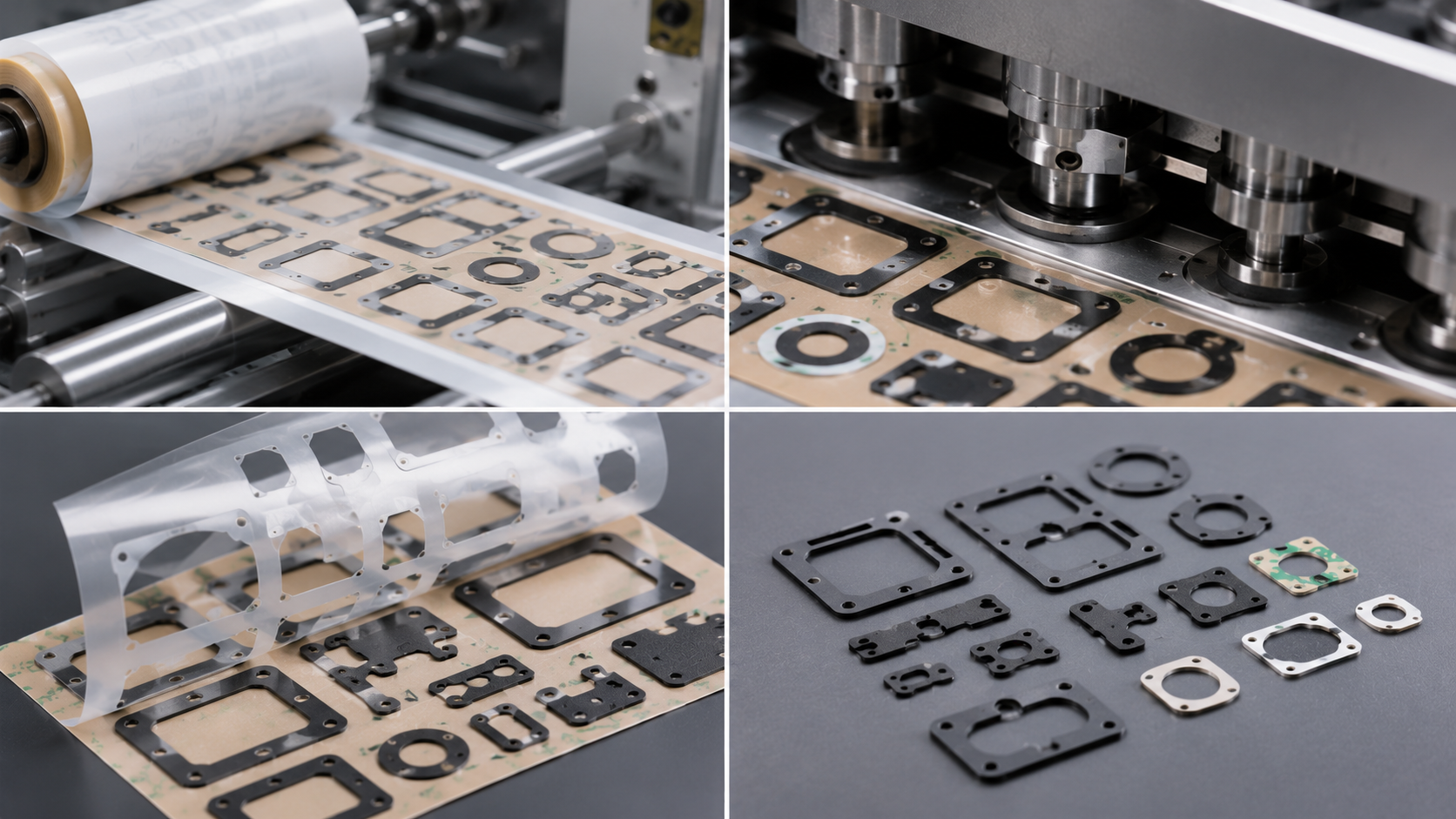
During die cutting, adhesive-backed materials are typically kiss-cut.
The cutting die penetrates:
- Face material
- Adhesive layer
But leaves:
- Release liner intact
When the operator peels the part from the liner, the adhesive must release cleanly without damaging the die-cut component.
If the release force exceeds the material's strength, tearing can occur.
Theme: Precision Kiss-Cut Die Cutting Process
Cause 1: Excessive Adhesive Strength
The most common cause of tearing is adhesive strength that exceeds the material's structural integrity.
This often occurs with:
- Thin PET films
- Non-woven materials
- Soft foam components
- Ultra-thin adhesive assemblies
When peeling begins, the adhesive remains attached to the liner too aggressively.
The material stretches until it eventually tears.
Common Symptoms
- Corner tearing
- Edge stretching
- Material elongation
- Adhesive transfer
Cause 2: Incorrect Release Liner Selection
Release liners are designed with specific release levels.
Examples include:
- Easy-release liners
- Medium-release liners
- Tight-release liners
If the liner release force is too high, operators must apply excessive peeling force.
This significantly increases the risk of damage.
Typical Problem Areas
- Small adhesive parts
- Thin film assemblies
- Complex geometries
- Automated dispensing systems
Selecting the proper liner often solves tearing issues without changing the adhesive.
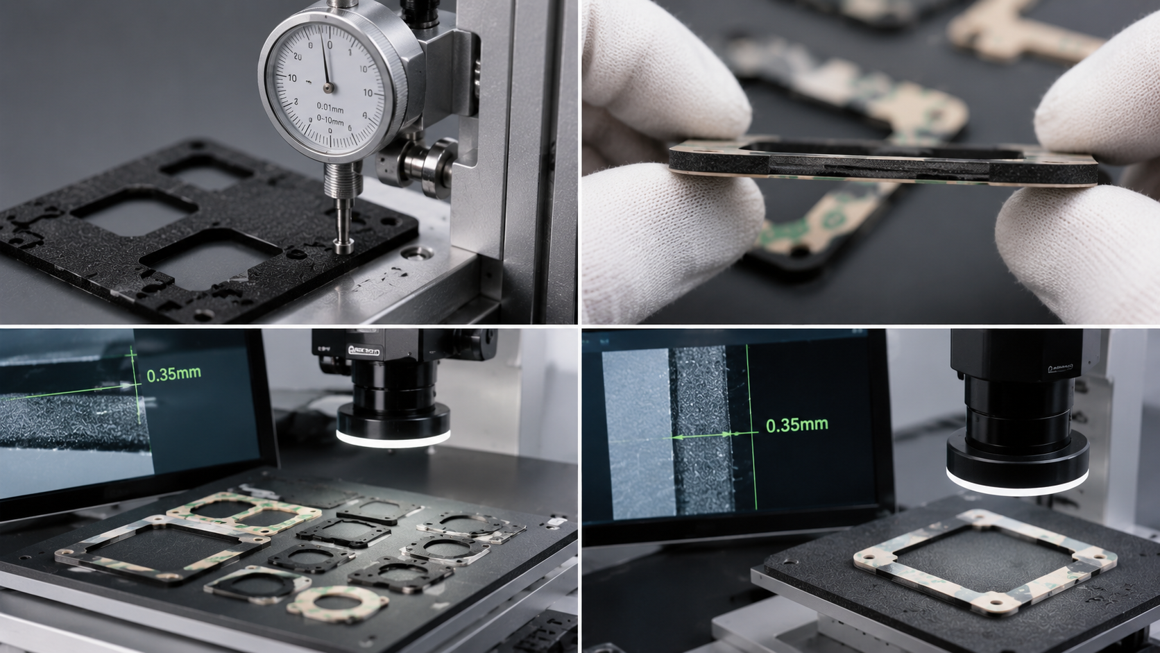
Cause 3: Poor Kiss-Cut Depth Control
Improper kiss-cutting can weaken the part before it reaches assembly.
Over-Cutting
If the die penetrates too deeply:
- Material edges become weakened
- Micro-cracks develop
- Structural integrity decreases
Under-Cutting
If cutting depth is insufficient:
- Parts remain partially attached
- Additional force is required during removal
Both situations can contribute to tearing.
Theme: Die Cut Depth Inspection
Cause 4: Weak Material Construction
Some materials are naturally more susceptible to tearing.
Higher-risk materials include:
- Thin non-woven fabrics
- Ultra-thin PET films
- Soft polyurethane foams
- Low-density foam materials
These materials may perform well in the final application but require careful converting design.
Lower-Risk Materials
- Cross-linked PE foam
- Reinforced films
- Thicker PET constructions
- High-density foam materials
Material selection should always consider converting requirements, not just final product performance.
Cause 5: Part Geometry Design
Part design plays a major role in liner removal performance.
Features that increase tearing risk include:
- Sharp internal corners
- Narrow bridges
- Small tabs
- Thin sections
- Complex cut patterns
These areas concentrate stress during peeling.
Design Improvements
Consider:
- Larger radii
- Wider bridges
- Increased material support
- Optimized peel direction
Small geometry changes often produce significant improvements.
Cause 6: Environmental Conditions
Temperature and humidity affect both adhesives and materials.
High Temperature
Can increase adhesive tack.
Results:
- Stronger liner attachment
- More difficult release
Low Temperature
Can make some materials brittle.
Results:
- Increased cracking
- Reduced flexibility
Environmental testing should be included during product validation.
Theme: Adhesive Component Assembly
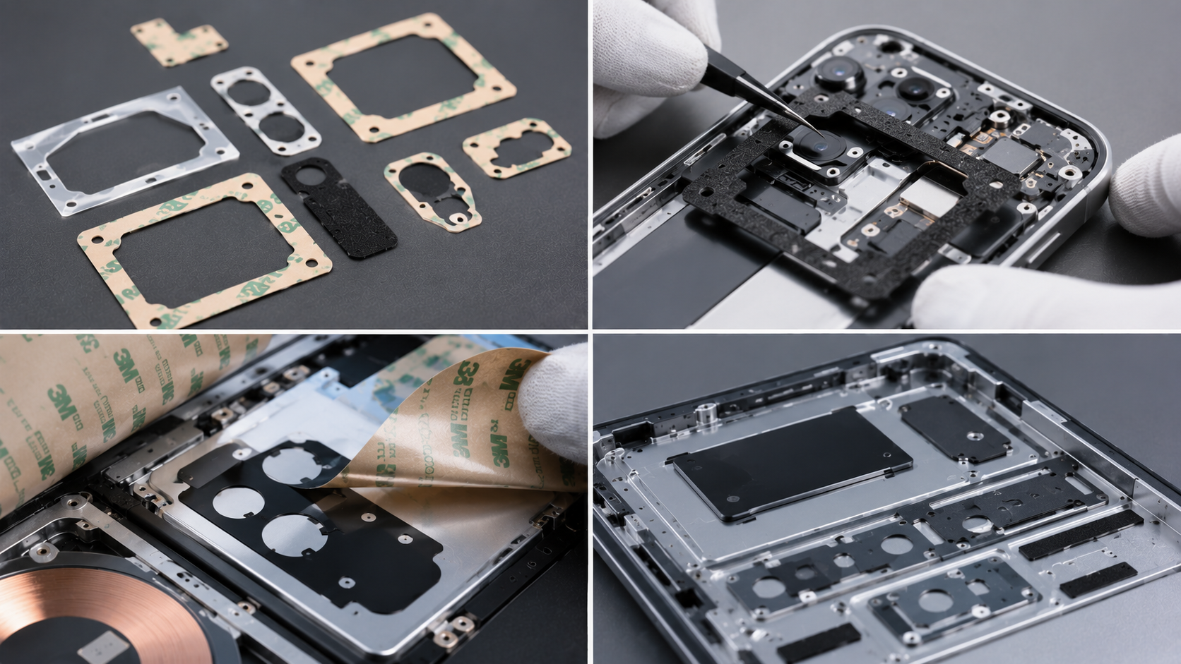
Cause 7: Improper Peel Angle
Operator technique can influence liner removal performance.
A poor peel angle may create excessive stress.
Recommended practice:
- Maintain consistent peel direction
- Use gradual removal
- Avoid sudden pulling motions
For automated assembly, peel angle should be validated during equipment setup.
How to Prevent Die Cut Parts from Tearing
Optimize Adhesive Selection
Choose an adhesive system appropriate for:
- Material strength
- Application requirements
- Assembly process
Match Release Liner to Adhesive
Balance:
- Adhesion performance
- Release force
Proper liner selection is often the simplest solution.
Improve Die-Cutting Accuracy
Maintain:
- Consistent kiss-cut depth
- Sharp tooling
- Stable process control
Validate Design Early
Evaluate:
- Peel force
- Corner integrity
- Automated dispensing performance
Before production release.
Conduct Aging Tests
Test after:
- 24 hours
- 72 hours
- Environmental exposure
Many liner-removal problems appear only after storage.
Quality Control Recommendations
Monitor:
- Release force
- Peel consistency
- Edge integrity
- Dimensional stability
- Material elongation
These metrics help identify issues before large-scale production.
How Sanken Manufacturing Prevents Liner Removal Failures
Dongguan Sanken Electronics Manufacturing Co., Ltd. specializes in precision die-cut components for automotive, consumer electronics, wearable devices, medical products, and industrial applications.
Our engineering team minimizes liner-removal failures through:
- Material compatibility analysis
- Precision kiss-cut control
- Release liner optimization
- Adhesive selection support
- Automated dispensing validation
- Environmental reliability testing
Key Advantages
- OEM and ODM customization
- ISO 9001 certified quality management
- RoHS and REACH compliant materials
- Domestic and overseas production bases
- Cleanroom precision manufacturing
- Tool development from drawings or samples
We support automotive NVH insulation components, optical films, adhesive assemblies, foam gaskets, and custom sealing solutions.
Featured Snippet Summary
Die-cut parts tear during liner removal primarily because of excessive adhesive strength, improper release liners, poor kiss-cut depth control, weak materials, unfavorable part geometry, or environmental factors. Preventing tearing requires balancing adhesive performance, liner release force, material strength, and die-cutting accuracy.
Conclusion
Tearing during liner removal is one of the most common challenges in precision die cutting. Although the failure often appears during assembly, the root cause usually originates earlier in material selection, adhesive design, liner specification, part geometry, or converting processes.
By optimizing these variables and validating performance under real production conditions, manufacturers can significantly reduce scrap, improve assembly efficiency, and ensure reliable product performance.