
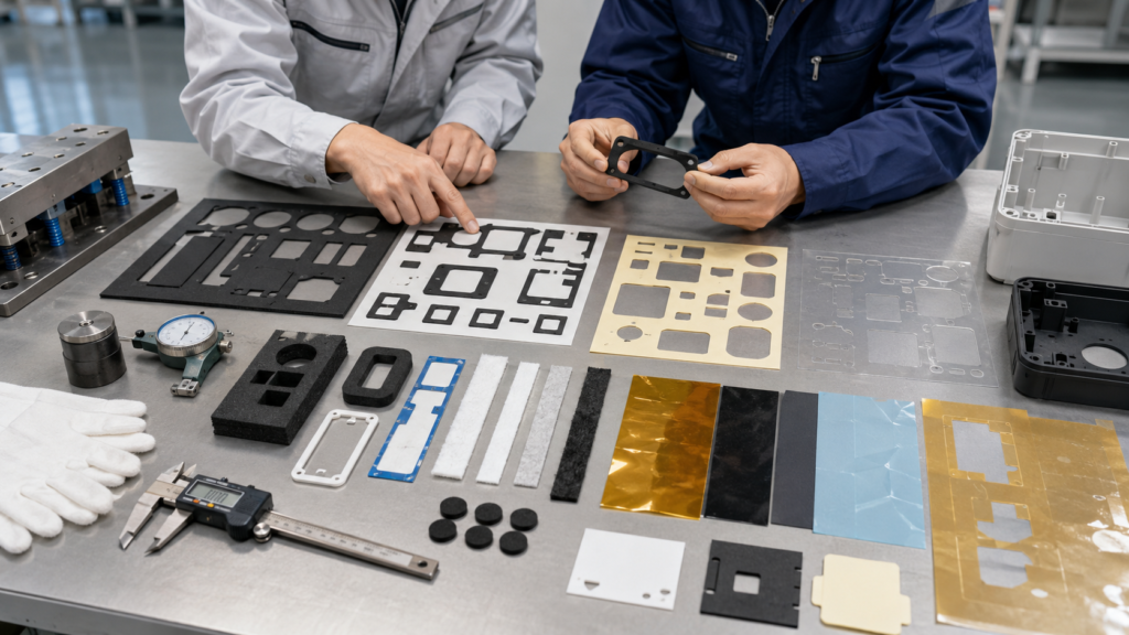
Designing die cut parts that reduce material waste and cost is not only a purchasing decision. It starts at the drawing stage. The shape, size, tolerance, adhesive structure, material thickness, part spacing, waste removal method, and packaging format all affect how efficiently a die cut component can be produced.
For OEM buyers and engineers, a small design change can sometimes reduce material waste, improve yield, shorten sampling time, and lower total assembly cost. A foam gasket with better nesting, a PET film with practical hole spacing, or an adhesive tape part with easier waste removal can be more cost-effective than a part designed only for appearance.
At Sanken, we help OEM customers develop custom die cut foam gaskets, adhesive tape components, PET and PI insulation films, protective films, rubber pads, non-woven felt parts, sealing components, and multilayer converted parts for automotive, electronics, battery, medical, appliance, and industrial applications.
Why Design Affects Die Cut Part Cost
Many people think die cut part cost mainly depends on material price. Material is important, but design has a major impact on cost.
A poorly designed part may cause high waste, slow production, difficult stripping, unstable tolerance, adhesive lifting, or repeated inspection failure. These issues increase the real cost even if the material itself is not expensive.
A well-designed die cut part should:
- Fit the final product
- Use material efficiently
- Avoid unnecessary tight tolerance
- Be easy to cut
- Be easy to remove from waste
- Stay stable on the liner
- Peel and apply smoothly
- Reduce rework during assembly
- Use practical packaging
Good die cut design is about balancing function, manufacturability, material utilization, and assembly efficiency.

Start With the Real Function of the Part
Before reducing cost, engineers should confirm what the part must do.
A die cut part may need to seal, bond, insulate, cushion, protect, block light, reduce vibration, control noise, or position another component. Cost reduction should never remove the function that the part needs to perform.
| Part Function | Common Materials | Design Focus |
|---|---|---|
| Sealing | Foam, rubber, silicone foam, EPDM foam | Gasket width, compression, gap fit |
| Bonding | Double-sided tape, transfer adhesive, foam tape | Adhesive area, liner release, pull tabs |
| Insulation | PET film, PI film, PC film | Hole alignment, edge quality, thickness |
| Cushioning | PE foam, PU foam, EVA foam | Compression, thickness, support area |
| Protection | Protective film, PET film | Surface coverage, easy removal, no residue |
| NVH control | Felt, foam, rubber | Contact area, anti-rattle position |
| Light blocking | Black PET, black foam, light-shielding tape | Window accuracy and clean edges |
If the supplier understands the function, they can suggest material and design improvements without weakening performance.
Improve Material Nesting
Material nesting means arranging parts on a sheet or roll in a way that uses the raw material efficiently. Poor nesting creates high waste.
Simple design changes can improve nesting:
- Reduce unnecessary outer size
- Avoid irregular shapes when possible
- Align parts in the same direction if material allows
- Use rounded shapes that can be arranged closer together
- Review spacing between parts
- Consider roll width before finalizing the part size
- Avoid large empty areas inside the layout
For roll-fed materials such as PET film, protective film, adhesive tape, and foam tape, part layout should match the material width. If the part is slightly wider than the usable roll width, the supplier may need to use a wider roll and create more waste.
For sheet materials such as foam, rubber, and felt, nesting affects how many parts can be cut from each sheet.
Good nesting can reduce cost without changing the part’s function.
Avoid Unnecessary Tight Tolerances
Tight tolerance increases cost because it requires better tooling, more process control, slower production, and more inspection.
Some dimensions are critical. Others may not need tight control.
Critical dimensions may include:
- Screw holes
- Positioning holes
- Sensor windows
- Gasket sealing width
- Adhesive bonding area
- Battery insulation clearance
- Display or optical openings
- Assembly contact edges
Non-critical outer edges, pull tabs, or handling areas may allow wider tolerance.
| Design Area | Tolerance Priority |
|---|---|
| Screw holes and positioning holes | High |
| Sealing path | High |
| Insulation clearance | High |
| Adhesive bonding area | Medium to high |
| Pull tab shape | Medium |
| Non-functional outer edge | Lower |
| Packaging spacing | Depends on assembly method |
For soft foam, rubber, felt, and adhesive tape, overly tight tolerance can increase rejection without improving performance. Practical tolerance should be based on material behavior and final assembly needs.
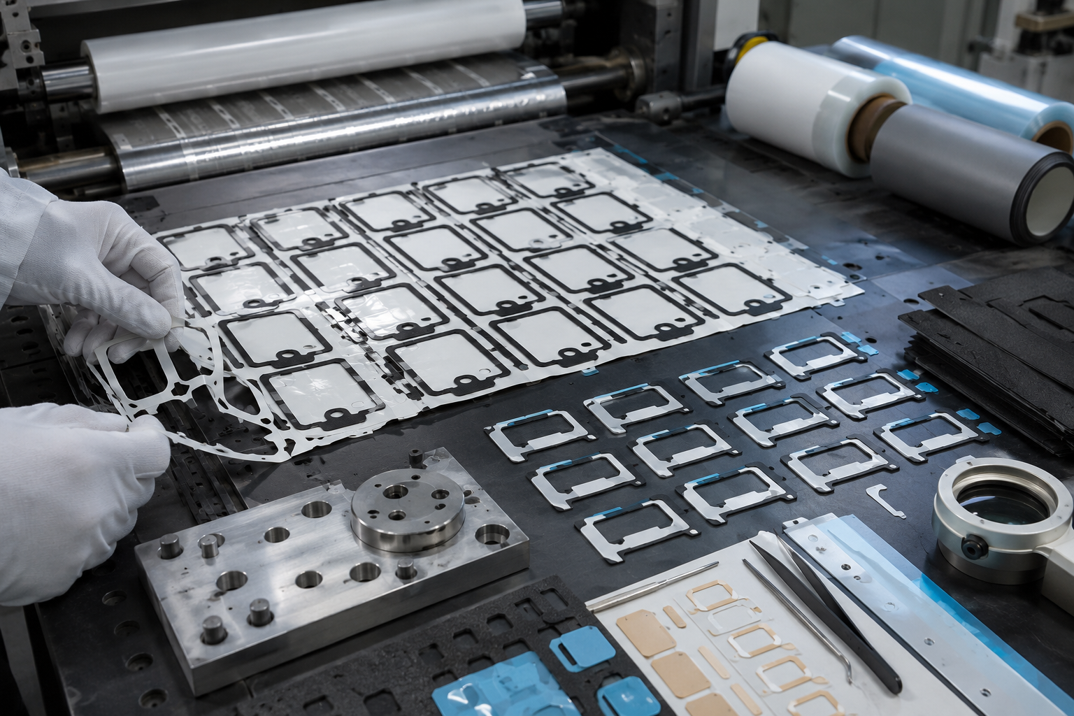
Design for Easier Waste Removal
Waste removal is one of the most important cost factors in die cutting. After cutting, unwanted material must be removed from around the part and from internal holes or windows.
Difficult waste removal slows production and increases scrap.
High-risk design features include:
- Very small holes
- Narrow slots
- Sharp internal corners
- Thin gasket walls
- Long thin strips
- Small isolated shapes
- Complex internal windows
- Weak bridges
- Dense part spacing
If waste breaks during removal, small pieces may remain on the liner or inside holes. This can cause inspection failure and assembly problems.
Useful design improvements include:
- Increase minimum hole size when possible
- Add corner radius
- Avoid very thin unsupported sections
- Increase wall width
- Simplify internal cutouts
- Add pull tabs for adhesive parts
- Adjust part spacing on liner
- Review waste matrix stripping direction
For adhesive-backed parts, waste removal is even more important because adhesive can stretch, string, or stick to finished parts.
Use Rounded Corners When Possible
Sharp corners may look clean on a drawing, but they can create problems during cutting, peeling, and assembly.
Sharp corners can cause:
- Adhesive lifting
- Foam tearing
- Film cracking
- Rubber burrs
- Waste removal difficulty
- Stress concentration
- Higher rejection rate
Rounded corners are often more stable and easier to produce. They can improve adhesive performance and reduce edge damage.
For foam gaskets, rounded corners help reduce tearing during waste removal. For adhesive tape parts, they reduce corner lifting after application. For PET and PI films, they improve handling and reduce stress at edges.
A small radius can often improve manufacturability without changing the part’s function.
Review Minimum Wall Width
Narrow walls are common in foam gaskets, adhesive tape frames, insulation films, and display-related parts. But if the wall is too narrow, the part may deform, tear, or fail during waste removal.
Minimum wall width depends on material type, thickness, adhesive backing, and tolerance requirement.
For example:
- Soft foam needs enough width to avoid stretching.
- Adhesive tape frames need enough bonding area.
- PET film frames need enough stability to avoid curling.
- Rubber frames need enough width to control rebound and edge quality.
A very narrow gasket may save material on paper, but it can increase scrap and assembly failure. A slightly wider wall may reduce total cost by improving yield and handling.
Choose the Right Material Thickness
Thicker material usually costs more because it uses more raw material and may require slower cutting. However, choosing material that is too thin can also create cost problems.
A foam gasket that is too thin may not seal.
A PET insulation film that is too thin may curl or fail the application requirement.
A rubber pad that is too thin may not damp vibration.
An adhesive tape that is too thin may not bond well to an uneven surface.
The best thickness is not always the thinnest option. It is the thickness that meets the function with stable production and assembly.
For foam, engineers should check gap size, compression ratio, density, and recovery.
For film, engineers should check insulation, flatness, hole accuracy, and handling.
For tape, engineers should check bonding surface, adhesive strength, liner release, and application pressure.
Simplify Multilayer Structures
Multilayer die cut parts can improve assembly efficiency, but they also increase cost if the structure is more complex than necessary.
Examples of multilayer parts include:
- Foam plus adhesive backing
- PET film plus double-sided tape
- Rubber plus adhesive layer
- Protective film plus pull tab
- Felt plus pressure-sensitive adhesive
- PI film plus liner
- Foam plus PET carrier layer
Each extra layer adds material cost, lamination time, alignment risk, thickness tolerance, and inspection needs.
Before choosing a multilayer structure, engineers should confirm whether each layer has a real function.
A simplified structure may reduce cost if it still meets sealing, bonding, insulation, protection, or assembly needs.
However, removing a layer only to reduce price can create new problems. For example, removing a carrier film may make a thin adhesive part harder to handle. Removing adhesive backing may slow customer assembly.
The goal is practical simplification, not blind cost cutting.
Optimize Adhesive and Liner Design
Adhesive-backed die cut parts are common in OEM manufacturing, but they can create waste and cost if not designed correctly.
Important adhesive design factors include:
- Adhesive type
- Adhesive thickness
- Carrier material
- Release liner
- Liner release force
- Kiss cutting depth
- Part spacing on liner
- Peel direction
- Pull tab design
- Packaging format
If the liner release is too tight, operators may deform parts during peeling. If release is too loose, parts may shift during shipping. If kiss cutting is too deep, the liner may tear. If it is too shallow, the part may not separate cleanly.
Adding pull tabs, split liners, or finger-lift areas can reduce assembly time and rework.
For cost reduction, adhesive should be selected based on bonding surface and environment, not simply maximum strength. Over-specified adhesive can increase cost and make handling more difficult.
Match Packaging to Assembly
Packaging affects both cost and usability.
A low-cost packaging method may seem attractive, but if it causes foam compression, film curling, adhesive shifting, or part deformation, the customer pays more during assembly.
Common packaging formats include:
- Loose parts
- Sheet format
- Roll format
- Liner-backed sheets
- Tray packaging
- Bagged sets
- Kitted components
- Assembly-ready layouts
Soft foam parts should avoid heavy stacking pressure. Thin PET or protective films should be kept flat. Small adhesive parts should remain stable on release liner. Complex parts may need organized trays or sheets.
Good packaging reduces handling time, counting errors, deformation, contamination, and rework.
Design for the Production Quantity
A prototype design may not be suitable for mass production.
For low-volume samples, flexible tooling and manual handling may be acceptable. For high-volume production, part layout, material roll width, stripping stability, inspection speed, and packaging efficiency become more important.
| Production Stage | Design Focus |
|---|---|
| Prototype | Confirm material, function, and basic fit |
| Pilot run | Check manufacturability, peeling, tolerance, packaging |
| Mass production | Optimize layout, yield, inspection, and assembly efficiency |
For high-volume OEM projects, small design issues can become expensive because they repeat thousands or millions of times.
How Sanken Helps Reduce Material Waste and Cost
Sanken Manufacturing Co., Ltd. helps OEM customers reduce die cut material waste and cost through early design review, material selection, adhesive lamination, die cutting process planning, tolerance review, and packaging optimization.
For foam gaskets, we review gasket width, foam density, compression, thickness, nesting, adhesive backing, and cutting feasibility.
For PET and PI insulation films, we review hole alignment, edge cleanliness, material layout, thickness, and assembly fit.
For adhesive tape parts, we review liner release, kiss cutting depth, pull tabs, part spacing, waste removal, and bonding surface.
For rubber and felt parts, we review hardness, rebound, edge control, fiber shedding, adhesive lamination, and packaging.
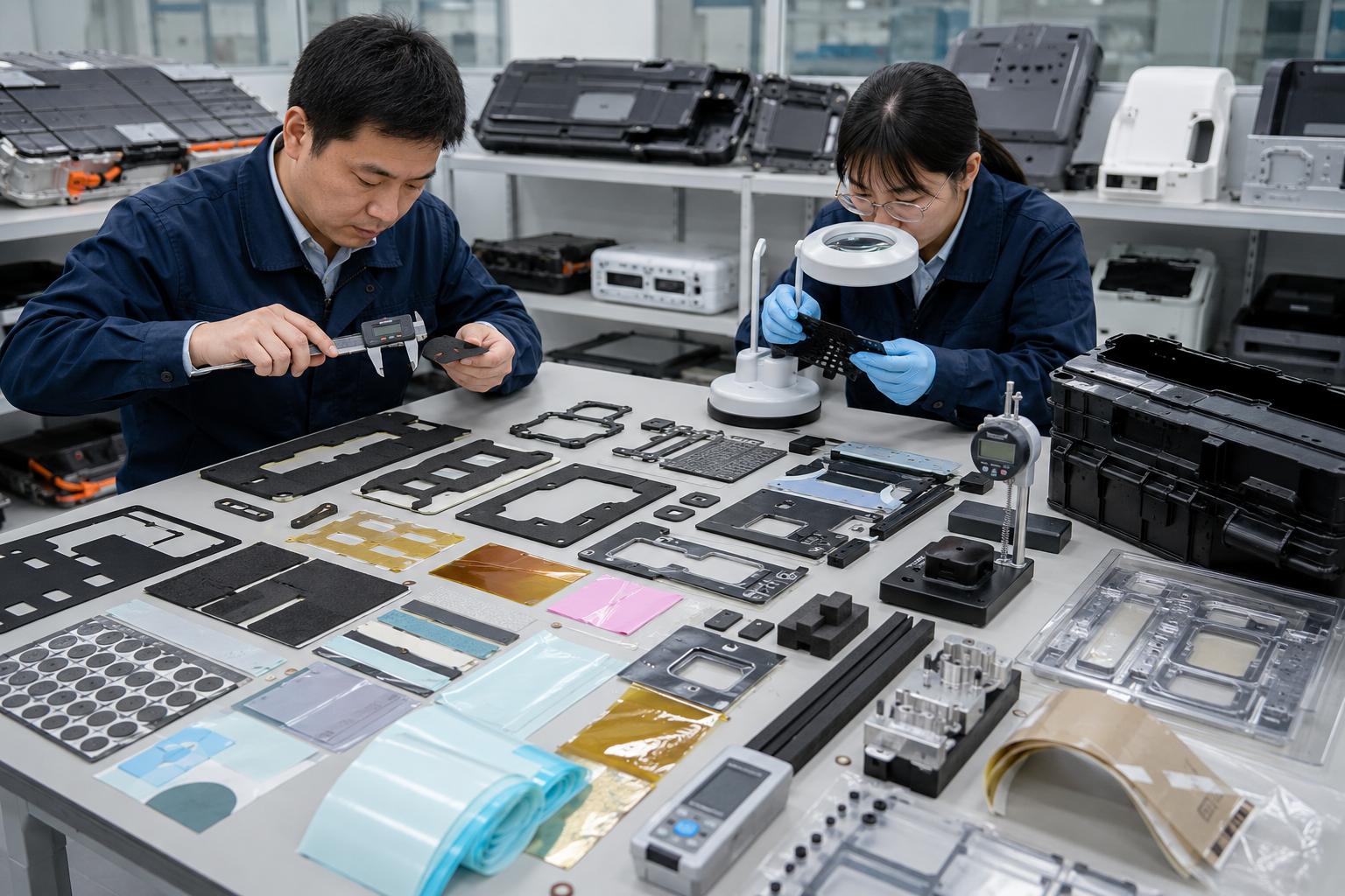
Our goal is to help customers reduce material waste, repeated sampling, difficult peeling, poor fit, inspection failure, assembly rework, and unstable mass production.
A cost-effective die cut part should not only be cheaper on the quotation. It should also be easier to produce, inspect, package, and assemble.
Conclusion
Designing die cut parts that reduce material waste and cost requires more than choosing a cheaper material. The most effective cost reduction comes from better part geometry, practical tolerance, efficient nesting, easier waste removal, suitable adhesive and liner design, correct material thickness, and assembly-friendly packaging.
For OEM buyers and engineers, early design review can prevent repeated samples, high scrap rate, difficult peeling, poor fit, and unnecessary production cost.
At Sanken, we help customers convert foam, rubber, PET film, PI film, adhesive tape, protective film, felt, and multilayer materials into custom die cut parts that balance function, manufacturability, material efficiency, and total OEM assembly cost.