
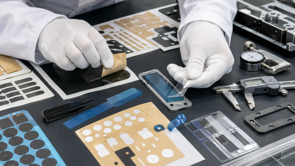
OEM die cut parts may look correct during sampling, but still fail during final assembly. A foam gasket may not align with the housing. A PET insulation film may block a screw hole. An adhesive tape part may stretch during peeling. A rubber pad may be too thick after compression. A protective film may curl and shift during placement.
When this happens, the problem is not only a “dimension issue.” Final assembly fit depends on material behavior, tolerance stack-up, adhesive structure, cutting accuracy, compression, packaging, handling, and the real assembly process.
For OEM buyers and engineers, preventing fit problems is important because poor-fitting die cut parts can cause rework, line delays, assembly stress, sealing failure, insulation risk, adhesive lifting, and higher total production cost.
At Sanken, we help OEM customers develop custom die cut foam gaskets, adhesive tape components, PET and PI insulation films, protective films, rubber pads, non-woven felt parts, sealing components, and multilayer converted parts for automotive, electronics, battery, medical, appliance, and industrial applications.
Why Die Cut Parts Fail to Fit During Final Assembly
A die cut part may pass basic dimension inspection but still fail during real product assembly. This is because final fit is affected by more than the part’s outer shape.
Common final assembly fit problems include:
- Hole position does not match screws or posts
- Foam gasket is too thick or too thin
- Adhesive-backed part stretches during peeling
- PET film curls after liner removal
- Rubber pad rebounds after cutting
- Part edge interferes with nearby components
- Protective film does not cover the correct area
- Gasket wall is too narrow to seal properly
- Multilayer materials are not aligned
- Packaging causes bending or compression marks
These problems are often discovered late, when the customer is already preparing for mass production. At that stage, any correction may require new tooling, new samples, material changes, or production delay.
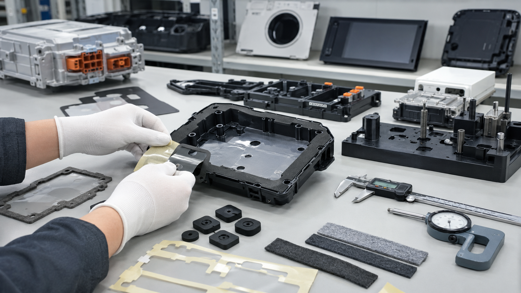
The Drawing May Not Reflect the Real Assembly
One common cause of poor fit is that the drawing does not fully reflect real product conditions.
A drawing may show a perfect housing, accurate hole positions, and a fixed gap. But in actual production, plastic molded parts, metal covers, battery housings, electronic modules, and appliance panels all have their own tolerances.
The die cut part must fit the real tolerance range, not only the ideal CAD drawing.
For example, a foam gasket may be designed for a 2.0 mm gap, but the real product gap may vary from 1.6 mm to 2.4 mm. If the foam thickness and compression range are not selected correctly, the gasket may be loose in one area and over-compressed in another.
A PET insulation film may match the drawing, but if the housing hole position shifts slightly during molding, the film may interfere with screws or connectors.
This is why die cut parts should be reviewed together with the real product, not only as a flat 2D shape.
Tolerance Stack-Up Is Often Ignored
Tolerance stack-up means that several small dimensional variations combine into a larger assembly problem.
A final assembly may include:
- Housing tolerance
- Die cut part tolerance
- Material thickness tolerance
- Adhesive thickness tolerance
- Hole position tolerance
- Foam compression variation
- Rubber rebound
- Assembly pressure variation
Each factor may look acceptable alone. But together, they may create poor fit.
| Fit Problem | Possible Tolerance Cause |
|---|---|
| Hole misalignment | Housing tolerance plus die cut hole position variation |
| Gasket too tight | Foam thickness plus small assembly gap |
| Poor sealing | Foam too thin plus large assembly gap |
| Tape edge interference | Outer profile tolerance plus adhesive flow |
| Film shift | Web tension variation plus thin film curling |
| Rubber pad mismatch | Rubber rebound plus loose tolerance control |
A reliable die cutting manufacturer should help buyers identify critical dimensions and review tolerance feasibility before tooling.
Material Behavior Changes During Cutting and Assembly
Different die cut materials behave differently. A dimension that is easy to control in PET film may be difficult in soft foam or rubber.
Foam can compress during cutting and recover later. Rubber can rebound after the blade passes through. Thin film can stretch or curl. Adhesive tape can shift during waste removal. Non-woven felt can deform or shed fibers if the edge is not controlled.
| Material | Common Fit Risk | What to Check |
|---|---|---|
| Foam | Compression, deformation, thickness variation | Density, thickness, compression ratio |
| Rubber | Rebound, hardness, edge burrs | Hardness, thickness, cutting method |
| PET / PI film | Hole shift, curling, edge quality | Web tension, flatness, hole accuracy |
| Adhesive tape | Stretching, adhesive overflow, liner release | Kiss cutting depth, carrier, liner |
| Protective film | Curling, poor placement, residue | Film tension, adhesive, packaging |
| Felt | Edge variation, fiber shedding | Density, cutting quality, adhesive backing |
The material should be chosen based on how it behaves in final assembly, not only how it looks after cutting.
Adhesive-Backed Parts May Deform During Peeling
Many OEM die cut parts are supplied with adhesive backing. These parts may fit correctly on the liner, but deform when operators peel and apply them.
Common adhesive-backed fit problems include:
- Foam gasket stretches during peeling
- PET adhesive film curls after liner removal
- Tape part shifts before placement
- Corners lift during application
- Liner release is too tight
- Liner tears and damages the part
- Adhesive overflows at the edge
- Part loses shape before bonding
For adhesive-backed parts, final fit depends on liner release, kiss cutting depth, adhesive strength, carrier stability, part geometry, and operator handling.
A pull tab, split liner, stronger carrier, wider wall, rounded corner, or better liner selection can often improve assembly fit.
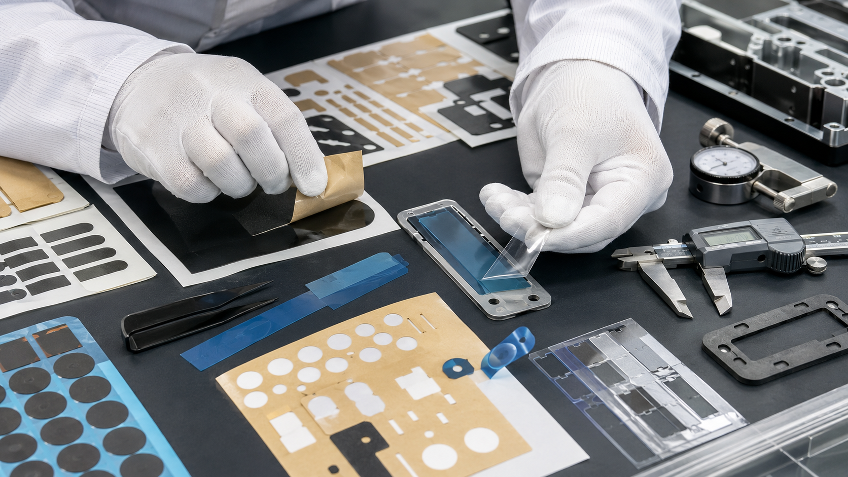
Foam Thickness and Compression Are Critical
Foam gaskets and foam pads often fail to fit because thickness and compression are not properly matched to the product gap.
If foam is too thin, it may not contact both surfaces. This can cause poor sealing, vibration, dust entry, or weak cushioning.
If foam is too thick, it may create excessive assembly force. This can deform plastic housings, push parts out of position, squeeze adhesive, or make screws difficult to tighten.
Engineers should review:
- Actual gap size
- Minimum and maximum gap
- Foam thickness
- Foam density
- Compression force
- Compression set
- Gasket width
- Adhesive thickness
- Final assembled thickness
The foam gasket should be tested in the real housing or a realistic assembly fixture before mass production.
Hole Alignment and Small Features Need Special Attention
Hole alignment is one of the most common reasons die cut parts fail during final assembly.
This is especially important for:
- PET insulation films
- PI battery insulation parts
- Protective films
- Foam gaskets
- Adhesive tape components
- Display bonding parts
- Sensor gaskets
- Rubber washers
Small holes, narrow slots, sharp corners, and thin walls can increase fit risk.
If the part has holes for screws, posts, terminals, connectors, clips, sensors, or cable openings, those dimensions should be treated as critical-to-quality features.
A good supplier should review whether the holes are large enough, whether the edge distance is safe, and whether the material can hold the required tolerance.
Packaging Can Change the Final Shape
Some die cut parts leave production in good condition but fail during customer assembly because packaging has changed their shape.
Packaging can cause:
- Foam compression marks
- Film curling
- Adhesive part shifting
- Liner bending
- Rubber pad deformation
- Scratched protective films
- Parts sticking together
- Edge damage
- Dust contamination
Soft foam should not be stacked under heavy pressure. Thin films should be kept flat. Adhesive-backed parts should remain stable on the release liner. Small parts may need tray packaging, sheet format, kitting, or controlled stacking.
Packaging is not only a shipping method. It is part of the assembly fit solution.
How to Prevent Final Assembly Fit Problems
The best way to prevent fit problems is to review the part as a functional component before mass production.
| Prevention Step | Why It Helps |
|---|---|
| Review real application | Confirms how the part will be used |
| Check actual assembly gap | Prevents wrong foam thickness |
| Identify critical dimensions | Focuses tolerance control where it matters |
| Test material behavior | Reduces compression, rebound, and curling risk |
| Review adhesive and liner | Improves peeling and placement |
| Use real assembly fixtures | Finds fit problems before production |
| Confirm packaging format | Prevents deformation before use |
| Run first article inspection | Confirms tooling and process stability |
| Test worst-case tolerance | Reduces mass production risk |
A sample should not only be checked flat on a table. It should be installed into the actual product whenever possible.
What Buyers Should Provide Before Tooling
To reduce fit issues, buyers should provide more than a drawing.
Useful project information includes:
- 2D or 3D drawing
- Real product sample
- Assembly location
- Critical dimensions
- Gap size
- Tolerance requirements
- Material preference
- Thickness requirement
- Adhesive requirement
- Bonding surface
- Assembly pressure
- Peeling method
- Testing requirement
- Packaging format
- Production quantity
For example, if a PET film is used near battery module screws, hole alignment is critical. If a foam gasket seals an automotive housing, compression and gap tolerance are critical. If an adhesive tape part is manually applied, liner release and handling design are critical.
How Sanken Helps Prevent Final Assembly Fit Problems
Sanken Manufacturing Co., Ltd. helps OEM customers reduce final assembly fit problems by reviewing material selection, die cut tolerance, adhesive structure, liner release, packaging, and real product assembly conditions.
For foam gaskets, we review thickness, density, compression ratio, sealing width, adhesive backing, and housing gap.
For PET and PI insulation films, we review hole alignment, edge cleanliness, dimensional stability, flatness, and surface quality.
For adhesive tape parts, we review liner release, kiss cutting depth, carrier stability, part spacing, pull tabs, and bonding surface.
For rubber and felt parts, we review hardness, rebound, fiber shedding, edge quality, adhesive lamination, and assembly fit.
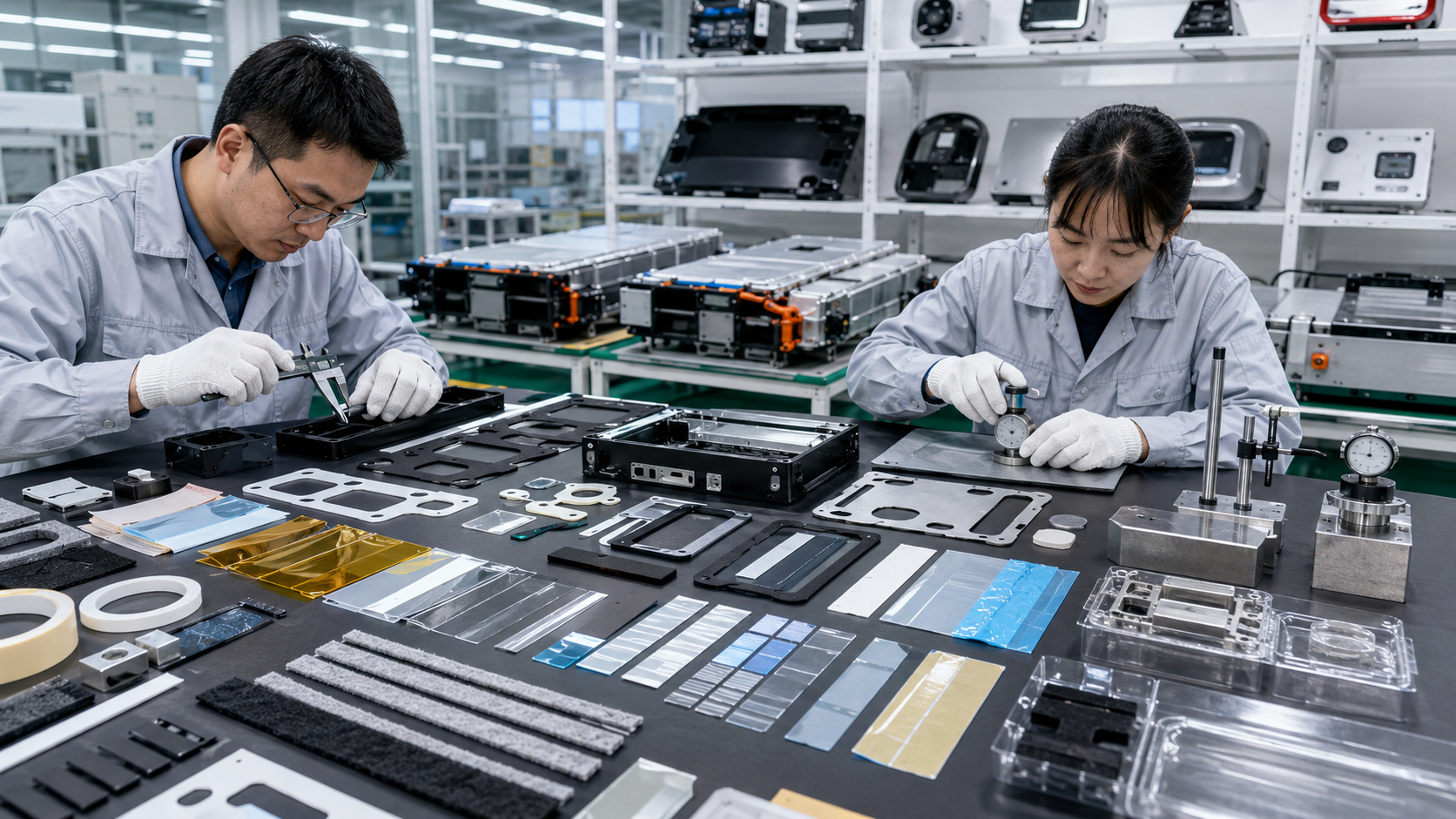
Our goal is to help customers reduce poor fit, hole mismatch, adhesive lifting, foam deformation, liner release issues, inspection failure, and repeated sampling.
A good die cut part should not only match the drawing. It should fit the real product, support efficient assembly, and remain stable in mass production.
FAQ
Why do OEM die cut parts not fit during final assembly?
They may not fit because of tolerance stack-up, wrong material thickness, foam compression problems, hole misalignment, adhesive deformation, film curling, rubber rebound, poor packaging, or drawing differences from the real product.
Why can a die cut part pass inspection but fail assembly?
A flat dimension check may not reflect real assembly conditions. The part may pass measurement but fail when compressed, peeled, bonded, bent, or installed into the final housing.
How can foam gasket fit problems be prevented?
Foam gasket fit problems can be prevented by checking the actual gap, foam thickness, density, compression ratio, gasket width, adhesive thickness, and real housing assembly conditions.
Why do adhesive-backed parts change shape during application?
Adhesive-backed parts may stretch, curl, or shift because of tight liner release, weak carrier material, soft foam, thin film, poor kiss cutting depth, or difficult part geometry.
What dimensions are most important for die cut assembly fit?
Critical dimensions usually include hole position, gasket width, outer profile, material thickness, adhesive position, liner spacing, and any area that contacts screws, clips, posts, connectors, or sealing surfaces.
Can packaging affect die cut part fit?
Yes. Poor packaging can cause foam compression, film curling, liner bending, adhesive shifting, edge damage, and deformation before the part reaches the assembly line.
Can Sanken help improve die cut part assembly fit?
Yes. Sanken supports material review, tolerance control, adhesive lamination, kiss cutting, liner release optimization, packaging review, and assembly-focused sample testing for custom OEM die cut parts.
Conclusion
OEM die cut parts do not fit during final assembly when material behavior, tolerance stack-up, adhesive structure, foam compression, hole alignment, packaging, or real assembly conditions are not fully controlled. A part may look correct on a drawing but still fail when it is peeled, compressed, positioned, or installed into the final product.
The best prevention method is early engineering review. Buyers and suppliers should review real product samples, critical dimensions, material behavior, adhesive performance, assembly gap, packaging, and testing before mass production.
At Sanken, we help OEM customers develop custom die cut foam, rubber, film, tape, felt, and multilayer components that are accurate, clean, easy to assemble, and stable in final product applications.