How Does Thickness Tolerance Affect Final Optical Component Fitting?
Thickness tolerance directly affects how an optical component fits, bonds, aligns, and performs inside the final assembly. In display modules, camera modules, sensor windows, optical films, protective covers, and adhesive spacers, even a small thickness deviation can cause air gaps, pressure marks, optical distortion, poor focus, bubble formation, weak bonding, or assembly failure.
For OEM buyers and engineers, the key question is not only “What thickness should this optical material be?” The better question is: “How much thickness variation can my optical assembly accept before performance, appearance, or reliability is affected?”
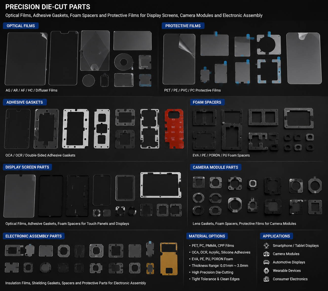
At Sanken Manufacturing, we help customers convert optical films, PET films, TPU films, adhesive layers, foam spacers, insulation films, protective films, and multilayer optical components into precision die-cut parts. For optical applications, controlling thickness tolerance is not just a quality detail. It is a core factor in stable fitting and final product performance.
What Is Thickness Tolerance?
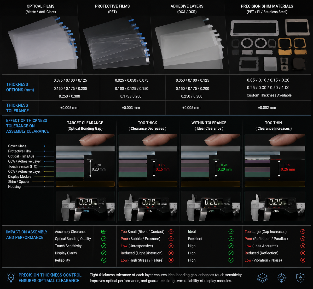
Thickness tolerance means the allowed variation between the specified material thickness and the actual measured thickness.
For example, if an optical film is specified as 0.10 mm with a tolerance of ±0.01 mm, the acceptable thickness range is 0.09 mm to 0.11 mm.
This may seem small, but in optical assemblies, small differences matter.
Optical components are often stacked in layers:
- Cover lens
- Optical clear adhesive
- Protective film
- Display film
- Touch sensor layer
- Spacer film
- Foam cushion
- Backing film
- Housing or frame
When every layer has thickness variation, the total stack-up tolerance can become much larger than expected.
This is why engineers must evaluate the full assembly, not only one material layer.
Why Thickness Tolerance Matters in Optical Fitting
Optical products often require tight control of spacing, flatness, pressure, and alignment.
Poor thickness control may cause:
- Uneven contact
- Air gaps
- Bubbles
- Newton rings
- Optical distortion
- Pressure marks
- Focus shift
- Touch sensitivity problems
- Assembly stress
- Poor adhesive bonding
For customers, these defects can lead to high rejection rates, visual complaints, and delayed production approval.
A material may look acceptable before assembly but fail after lamination because the thickness variation creates local pressure or trapped air.
Impact on Adhesive Bonding
Adhesive layers are highly sensitive to thickness variation.
If the optical film or spacer is too thick in one area, it may create uneven pressure during lamination. If it is too thin, it may not contact the bonding surface fully.
This can cause:
- Bubbles
- Edge lifting
- Weak peel strength
- Uneven wet-out
- Delamination
- Visible bonding marks
For optical clear adhesive applications, thickness control is especially important because the adhesive must spread evenly without trapping air.
In display and camera module assembly, poor bonding can affect both appearance and reliability.
Impact on Optical Clarity
Thickness variation can affect how light passes through the component.
In optical films and display structures, uneven thickness may create:
- Haze variation
- Reflection differences
- Light leakage
- Color inconsistency
- Distortion
- Bright spots
- Shadow lines
For matte films, anti-glare films, protective films, and display films, consistent thickness helps maintain uniform visual performance across the surface.
If the material is thicker in one area, the display may show uneven light transmission. If the adhesive layer is inconsistent, the user may see bubbles or rainbow-like patterns.
Impact on Camera Module Focus and Alignment
Miniature camera modules are extremely sensitive to spacing.
A small thickness change in a foam pad, adhesive gasket, optical spacer, or protective film may shift the lens, sensor, or housing position.
This can affect:
- Focus accuracy
- Image sharpness
- Lens alignment
- Vibration stability
- Dust sealing
- Module height
- Assembly pressure
If a foam cushion is too thick, it may push the module out of position.
If it is too thin, it may fail to support or damp vibration.
If an adhesive spacer is uneven, it may tilt the optical path.
For camera modules, thickness tolerance is directly connected to image quality.
Impact on Touch Display Assembly
Touch display assemblies require stable layer spacing and flat bonding.
Thickness variation may cause:
- Poor touch response
- Local pressure points
- Display mura
- Uneven lamination
- Edge lifting
- Sensor misalignment
- Cover glass stress
In touch displays, different layers must work together without creating stress.
If a die-cut film or spacer does not hold stable thickness, it may create pressure between the touch sensor and display layer. This can affect sensitivity or create visible marks.
For automotive displays, tablets, industrial panels, and medical screens, this can become a serious quality issue.
Stack-Up Tolerance: The Hidden Risk
One of the biggest risks in optical assembly is stack-up tolerance.
Each material layer may be within its own tolerance, but the combined variation may still create a fitting problem.
For example:
| Layer | Nominal Thickness | Tolerance |
|---|---|---|
| Protective film | 0.05 mm | ±0.005 mm |
| Optical adhesive | 0.10 mm | ±0.010 mm |
| PET spacer | 0.08 mm | ±0.008 mm |
| Foam cushion | 0.30 mm | ±0.030 mm |
| Release liner effect | Process-dependent | Variable |
Individually, each material may be acceptable.
But together, the total variation may affect final fit.
This is why optical component design should review the complete material stack before mass production.
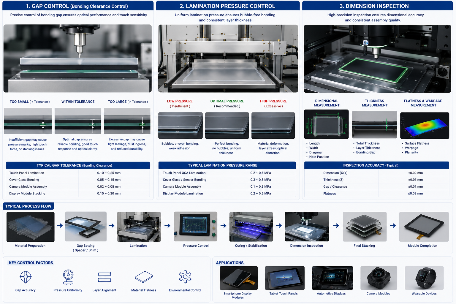
How Die Cutting Can Affect Thickness Stability
Die cutting does not usually change the base material thickness, but it can affect the final part condition.
For soft materials such as foam, adhesive, rubber, and non-woven layers, cutting pressure may compress the material. After cutting, the material may rebound unevenly.
Possible issues include:
- Edge compression
- Adhesive overflow
- Liner deformation
- Local thickness change
- Warped parts
- Uneven flatness
- Difficult waste stripping
For optical components, these issues can become visible defects after assembly.
This is why precision die cutting requires controlled tooling pressure, sharp dies, stable material tension, and proper waste removal.
Materials That Need Extra Thickness Control
Some materials are more sensitive than others.
| Material | Thickness Concern |
|---|---|
| Optical PET film | Visual uniformity and alignment |
| TPU film | Flexibility and dimensional stability |
| Optical clear adhesive | Bubble control and wet-out |
| Foam spacer | Compression and support height |
| Silicone adhesive layer | Bonding and removability |
| Protective film | Surface protection and release behavior |
| Non-woven layer | Compression and fiber structure variation |
| Rubber gasket | Sealing pressure and rebound |
For rigid optical films, thickness affects clarity and fit.
For soft cushioning layers, thickness affects pressure and compression recovery.
For adhesive materials, thickness affects bonding strength and bubble risk.
Common Problems Caused by Poor Thickness Tolerance
1. Assembly Gap Variation
The part may not sit flush inside the housing or frame.
2. Bubble Formation
Uneven thickness can trap air during lamination.
3. Pressure Marks
A thick area may press against a display or optical surface.
4. Weak Bonding
A thin area may not fully contact the bonding surface.
5. Optical Distortion
Light transmission may become uneven.
6. Poor Fit During Automation
Automated assembly equipment may reject parts if thickness variation affects pickup, placement, or pressure.
7. Long-Term Reliability Issues
Even if the part passes initial inspection, stress from uneven thickness may cause lifting, warping, or delamination over time.
How to Control Thickness Tolerance in Optical Components
Thickness control starts before production.
Buyers should work with suppliers to confirm:
- Material thickness specification
- Acceptable tolerance range
- Critical functional areas
- Stack-up tolerance
- Lamination pressure
- Die-cutting method
- Inspection method
- Packaging and storage conditions
- Assembly pressure requirement
- Final product testing standard
A good supplier should not only cut the material. They should understand how the finished part fits into the customer’s assembly.
Design Tips for Better Optical Fitting
Engineers can reduce fitting problems by applying practical design rules.
Use Realistic Tolerances
Do not demand unnecessarily tight tolerances if the material cannot hold them consistently.
Review the Full Stack
Do not evaluate one film or spacer alone. Review all layers together.
Avoid Over-Compression
Soft foam or adhesive layers should not be forced beyond their functional compression range.
Add Assembly Clearance
Where possible, allow enough clearance for normal material variation.
Test Under Real Conditions
Test after lamination, aging, heat exposure, and handling. Initial appearance is not enough.
Choose Stable Materials
Use optical-grade films, controlled adhesive layers, and reliable spacer materials for critical applications.
What Buyers Should Confirm Before Ordering
Before sourcing optical die-cut components, buyers should ask:
- What is the required nominal thickness?
- What tolerance is functionally necessary?
- Which areas are most sensitive to thickness change?
- Is the material rigid, flexible, adhesive-backed, or compressible?
- Will the part be laminated?
- Will it contact glass, sensor, display, or lens components?
- Does the assembly require air-gap control?
- Will it face heat, humidity, or long-term compression?
- How will thickness be inspected?
- Can the supplier support prototype testing and mass production?
These questions help avoid late-stage fitting failures.
How Sanken Helps Customers Control Optical Component Fit
At Sanken Manufacturing, we help customers develop optical and electronic auxiliary materials with controlled converting processes.
Our support includes:
- Optical film die cutting
- PET and TPU film converting
- Adhesive lamination
- Foam spacer die cutting
- Protective film converting
- Kiss cutting
- Waste stripping control
- Dimensional inspection
- Prototype and mass production support
- Custom multilayer component assembly
We help customers reduce common problems such as bubbles, edge lifting, dimensional mismatch, poor adhesive wet-out, pressure marks, and assembly instability.
For OEM buyers, this means fewer trials, more stable production, and better final product quality.
Conclusion
Thickness tolerance affects final optical component fitting by controlling spacing, pressure, bonding, flatness, alignment, and visual performance. In display films, camera modules, touch panels, protective films, and optical adhesive parts, even small thickness variation can lead to bubbles, pressure marks, poor focus, weak bonding, or assembly failure.
For reliable optical assemblies, buyers should evaluate the complete material stack, not just one layer. At Sanken Manufacturing, we help customers select, laminate, die cut, and convert optical materials into precision components that fit correctly and perform consistently in final products.