
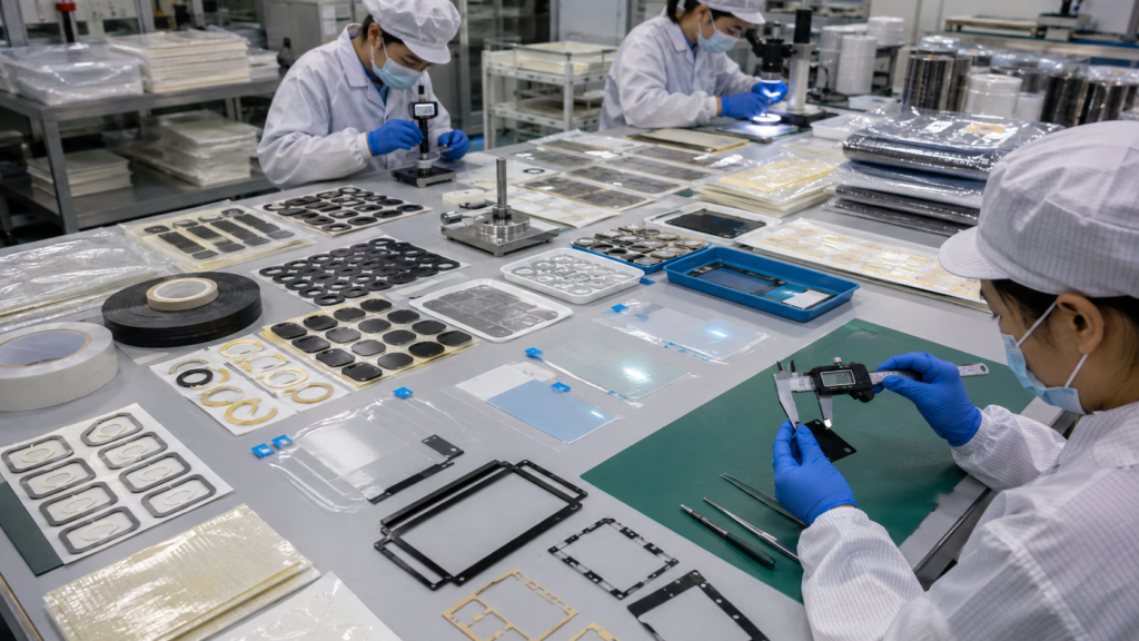
Die cutting and kiss cutting are closely related converting processes, but they produce different part structures and delivery formats. The correct method depends on whether an OEM needs individual components, adhesive parts retained on a release liner, easy-peel protective films, roll-fed components, or sheet-form parts prepared for manual or automated assembly.
For adhesive tapes and protective films, the cutting depth is especially important. A complete through cut separates the finished component from every material layer. A kiss cut cuts the functional material while leaving the release liner or carrier layer intact. This difference affects handling, peeling, positioning, packaging, production speed, and total assembly cost.
OEM buyers should therefore evaluate more than the drawing shape. Material structure, liner design, part thickness, cutting tolerance, waste removal, application method, and delivery format must be considered together.
Sanken supports OEM projects through precision die cutting services for adhesive tapes, protective films, foam components, PET films, black light-blocking films, and multilayer converted parts.
Die Cutting and Kiss Cutting Use Different Cutting Depths
The fundamental difference between die cutting and kiss cutting is how deeply the tool passes through the material structure.
In a through-cut operation, the cutting tool passes through the functional material, adhesive layer, and liner. The finished part is completely separated from the surrounding material.
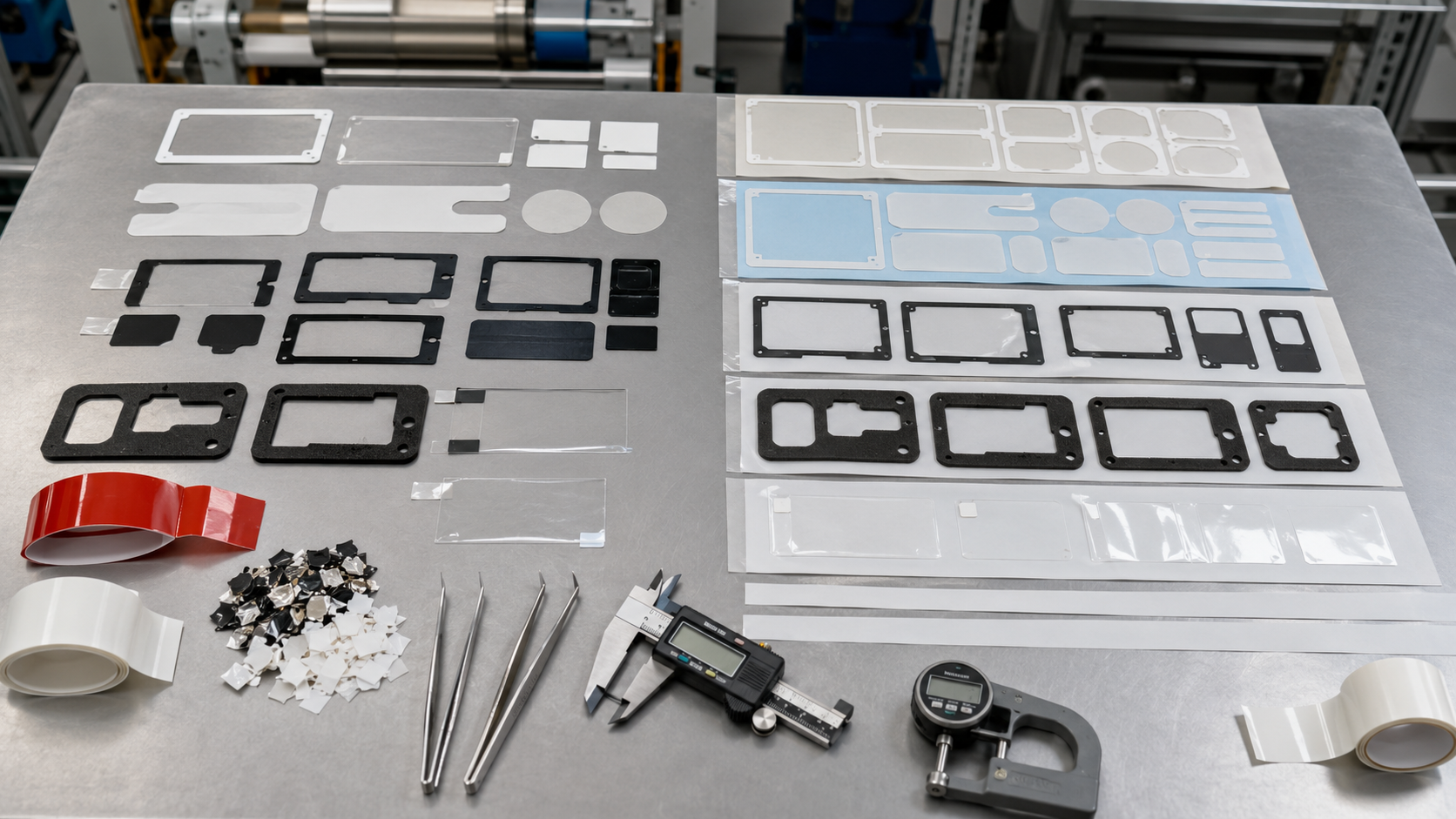
In a kiss-cut operation, the cutting tool passes through the upper material and adhesive but stops before cutting through the supporting release liner. The converted components remain attached to the liner until they are peeled off during assembly.
| Process | Cutting Depth | Finished Delivery Format | Common Use |
|---|---|---|---|
| Through cutting | Through all layers | Individual parts or fully separated shapes | Foam pads, rubber gaskets, film components and loose parts |
| Kiss cutting | Through the functional layers only | Parts retained on a release liner | Adhesive tape parts, protective films and thin film components |
| Perimeter kiss cutting | Cuts the outline while preserving the liner | Sheet- or roll-supported components | Frames, rings, strips and windows |
| Combination cutting | Different depths within one structure | Multilayer assembly-ready parts | Pull tabs, split liners and complex adhesive components |
The required cutting depth should be clearly identified in the drawing or technical specification. Simply writing “die cut part” may not provide enough information for the converter to determine the intended delivery structure.
Through-Cut Parts Provide Complete Separation
Through cutting is suitable when the customer needs fully separated components. It is commonly used for foam pads, rubber pieces, PET insulation films, felt parts, and some protective film shapes.
The main advantages include:
- Fully separated finished parts
- Simple part counting
- Flexible tray or bag packaging
- Easy integration into assembly kits
- Suitability for thicker materials
- Compatibility with components that do not require a liner
However, loose parts may be harder to handle when they are thin, flexible, adhesive-backed, or very small. Operators may have difficulty finding the correct orientation or removing a release liner from each individual part.
Through-cut components can also move, curl, stick together, or become contaminated if their packaging is not properly designed. For adhesive products, each part may require an individual liner or a structured carrier to protect the exposed adhesive.
Sanken can supply custom die cut parts for OEM assembly in sheets, individual pieces, liner-supported layouts, and assembly-ready packaging depending on the part structure.
Kiss-Cut Formats Improve Handling of Adhesive Parts
Kiss cutting is particularly useful for pressure-sensitive adhesive materials. The parts remain organized on the original release liner after cutting and waste removal.
Common kiss-cut adhesive components include:
- Double-sided adhesive frames
- Transfer adhesive shapes
- PET-backed adhesive components
- Foam tape gaskets
- Adhesive mounting strips
- Thin bonding rings
- Pull-tab adhesive parts
- Black light-blocking adhesive frames
Keeping the parts on a liner provides several assembly advantages. Operators can see the part orientation, peel one component at a time, and apply it without searching through loose pieces. The liner also protects the adhesive from dust, fingers, and accidental contact.
Kiss-cut parts can be supplied in:
| Delivery Format | Typical Benefit |
|---|---|
| Individual liner squares | Simple manual application |
| Multi-part sheets | Efficient handling of several components |
| Continuous rolls | Suitable for high-volume or automated assembly |
| Indexed liner strips | Supports repeatable pick-and-place operations |
| Kitted sheets | Keeps related parts together in assembly order |
For high-volume projects, roll-to-roll precision die cutting can support consistent spacing and controlled part presentation when the material and part design are suitable.
Protective Films Depend on Controlled Liner and Tab Design
Protective films are used to prevent scratches, dust, fingerprints, and handling damage on displays, plastic housings, glass surfaces, metal panels, and coated components.
Kiss cutting is often preferred because the protective film remains flat and supported before application. The surrounding waste matrix can be removed while the finished films stay arranged on the release liner.
Typical protective film features include:
- Camera or sensor openings
- Display windows
- Positioning holes
- Removal tabs
- Extended liners
- Split liners
- Easy-peel corners
- Custom outer profiles
A pull tab may be created from the protective film itself, from an extended liner, or from an additional laminated layer. The best structure depends on whether the operator applies or removes the film, which side is accessible, and how much space is available.
Protective films must also use an appropriate adhesion level. A film with insufficient adhesion may lift during production. Excessive adhesion may make removal difficult or leave residue on the protected surface.
Material Structure Determines the Correct Process
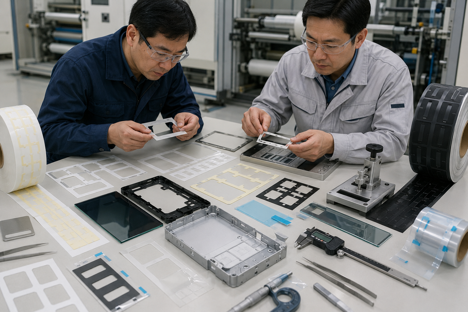
The cutting method cannot be selected independently from the material construction. Adhesive parts and protective films may include several thin layers with different mechanical properties.
A typical structure may contain:
- Functional film, foam or tape
- Pressure-sensitive adhesive
- Carrier film, where applicable
- Release coating
- Paper or film release liner
Each layer affects cutting performance. A thin PET film behaves differently from soft foam tape. Transfer adhesive has no supporting carrier and may stretch or distort during waste removal. A protective film may curl when released from its liner. Thick foam may compress under the tool before it is cut.
| Material Structure | Common Processing Concern |
|---|---|
| Double-sided tape with PET carrier | Adhesive edge control and liner depth |
| Transfer adhesive | Stretching and difficult waste removal |
| Foam tape | Compression, adhesive overflow and narrow borders |
| PET-backed adhesive film | Film burrs, flatness and hole accuracy |
| Protective film | Scratches, curling and residue control |
| Black light-blocking film | Window accuracy and clean edges |
For adhesive-backed foam frames and sealing components, the foam thickness, adhesive type, liner release, and narrow wall width should be reviewed together. Sanken’s foam gaskets and sealing components can be converted with adhesive backing and suitable liner formats for OEM installation.
Release Liners Are Part of the Component Design
The release liner is sometimes treated as disposable packaging, but it is an important part of the manufacturing and assembly system.
A suitable liner should:
- Protect the adhesive surface
- Remain flat during cutting
- Support controlled kiss-cut depth
- Release the part without stretching it
- Resist tearing during waste removal
- Work with manual or automated application
- Maintain part spacing during shipment
Paper liners may provide stiffness and cost efficiency, while film liners can offer better dimensional stability, smoothness, or transparency. Release force must also be matched to the adhesive and peeling direction.
If the release force is too high, operators may deform thin parts during removal. If it is too low, components may shift or detach during transport. Split liners and extended liner tabs can make larger adhesive components easier to apply without touching the bonding surface.
The release liner should therefore be confirmed during sampling rather than after the adhesive part reaches the customer’s production line.
Tolerance, Tooling, and Waste Removal Affect Quality
Both die cutting and kiss cutting require controlled tooling, but kiss cutting places additional demands on depth accuracy.
Too much cutting pressure may damage or penetrate the liner. Too little pressure may leave the adhesive or film incompletely cut, causing tearing during peeling.
Important production controls include:
- Tool sharpness
- Cutting pressure
- Material thickness variation
- Liner thickness
- Adhesive flow
- Web tension
- Registration accuracy
- Waste matrix removal
- Part spacing
- Tool wear
Narrow adhesive frames and small holes require particular attention. Adhesive can move under pressure, and thin borders may stretch during waste removal. Sharp internal corners may also become lifting or tearing points.
Prototype samples should be evaluated using the actual material construction, not only a material of similar thickness. Changes in adhesive, liner, foam density, or film stiffness can alter the cutting result.
Assembly Method Should Guide the Delivery Format
The customer’s installation process is often the deciding factor between through-cut and kiss-cut parts.
Through-cut parts may be suitable when operators place larger foam pads into fixtures or when components are supplied as part of a kit. Kiss-cut formats are usually more efficient when operators must peel and apply small adhesive components repeatedly.
| Assembly Method | Recommended Format |
|---|---|
| Manual placement of larger non-adhesive parts | Through-cut individual components |
| Manual application of small adhesive parts | Kiss-cut sheets with easy-peel liners |
| Automated pick-and-place | Indexed roll or stable carrier format |
| Multi-part assembly station | Kitted liner sheets |
| Protective film application | Kiss-cut films with tabs or split liners |
| Service or replacement kits | Individually lined or separated parts |
OEM buyers should provide information about peeling direction, application speed, operator access, automation equipment, and preferred packaging during the quotation stage. These details can prevent a technically accurate part from becoming difficult to use on the production line.
Cost Depends on the Complete Converting Structure
Kiss cutting is not automatically more or less expensive than through cutting. Total cost depends on the material, tooling, liner, part layout, waste percentage, production volume, and packaging method.
A kiss-cut format may require more process control, but it can reduce downstream labor and assembly mistakes. A through-cut part may be simpler to manufacture but require more packaging, sorting, or manual liner removal.
Cost factors include:
- Tooling type and complexity
- Number of material layers
- Part dimensions and spacing
- Waste matrix removal difficulty
- Liner specification
- Sheet or roll presentation
- Inspection requirements
- Packaging format
- Annual volume
The lowest converted part price may not produce the lowest total assembly cost. OEM buyers should compare material cost, converting cost, operator handling, placement accuracy, rework, and production speed.
Quality Checks for Adhesive Parts and Protective Films
Quality inspection should reflect both dimensional requirements and practical assembly performance.
| Inspection Item | Purpose |
|---|---|
| Outer dimensions | Confirms part fit |
| Hole and window position | Prevents interference |
| Kiss-cut depth | Protects liner integrity |
| Liner release | Supports smooth peeling |
| Adhesive edge quality | Prevents overflow and contamination |
| Film surface | Detects scratches, dust and marks |
| Part flatness | Reduces curling and lifting |
| Waste removal quality | Prevents unwanted material around parts |
| Sheet or roll spacing | Supports consistent application |
| Packaging condition | Protects parts during transport |
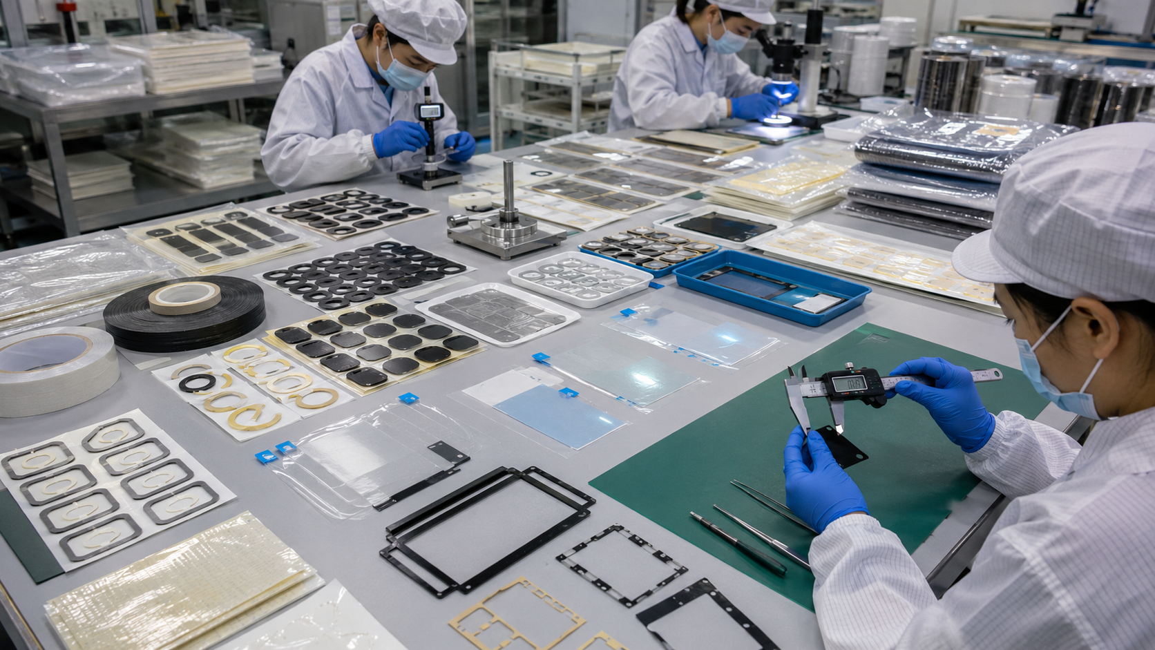
Peel trials on the actual assembly surface are recommended for adhesive components. Protective films should also be tested for application stability, removal force, and residue after the intended storage period.
How Sanken Supports OEM Die Cut and Kiss Cut Projects
Sanken supports adhesive tape and protective film projects from drawing review and material converting through sample development and mass production.
Relevant capabilities include:
- Precision die cutting and kiss cutting
- Adhesive lamination
- Double-sided tape converting
- Transfer adhesive converting
- Foam tape components
- PET-backed adhesive parts
- Protective films with pull tabs
- Black light-blocking film frames
- Release liner and carrier design
- Sheet and roll delivery formats
- Multilayer converted components
- Inspection and assembly-ready packaging
For each project, Sanken reviews the material stack, cutting depth, adhesive behavior, liner structure, part geometry, tolerance, peeling method, waste removal, packaging, and final assembly process.
The objective is to supply parts that are not only dimensionally correct but also easy to peel, position, apply, and integrate into stable OEM production.
You May Also Be Interested In
- How to Prevent Adhesive Lifting in Die Cut Tape Components
- How to Choose the Right Pressure Sensitive Adhesive Tape for Die-Cut Parts
- Pressure Sensitive Adhesive Tape for OEM Applications: What Buyers Should Know
- Laser Cutting vs Die Cutting: Which Is Better for Foam, Tape, Film, and Rubber Parts?
- What Is the Difference Between Perforation and Die Cutting for Flexible Materials?
Conclusion
Die cutting and kiss cutting serve different purposes in OEM material converting. Through cutting completely separates the component, while kiss cutting preserves the release liner beneath adhesive tapes, protective films, and other thin converted parts.
The correct process depends on material structure, cutting depth, liner design, tolerance, part geometry, waste removal, assembly method, and packaging format. For adhesive components, a carefully designed kiss-cut liner can improve peeling, positioning, cleanliness, and production speed. For larger or non-adhesive components, through-cut delivery may provide a simpler solution.
Sanken helps OEM buyers evaluate these factors and develop custom adhesive parts and protective films that support reliable handling from sample validation through mass production.