
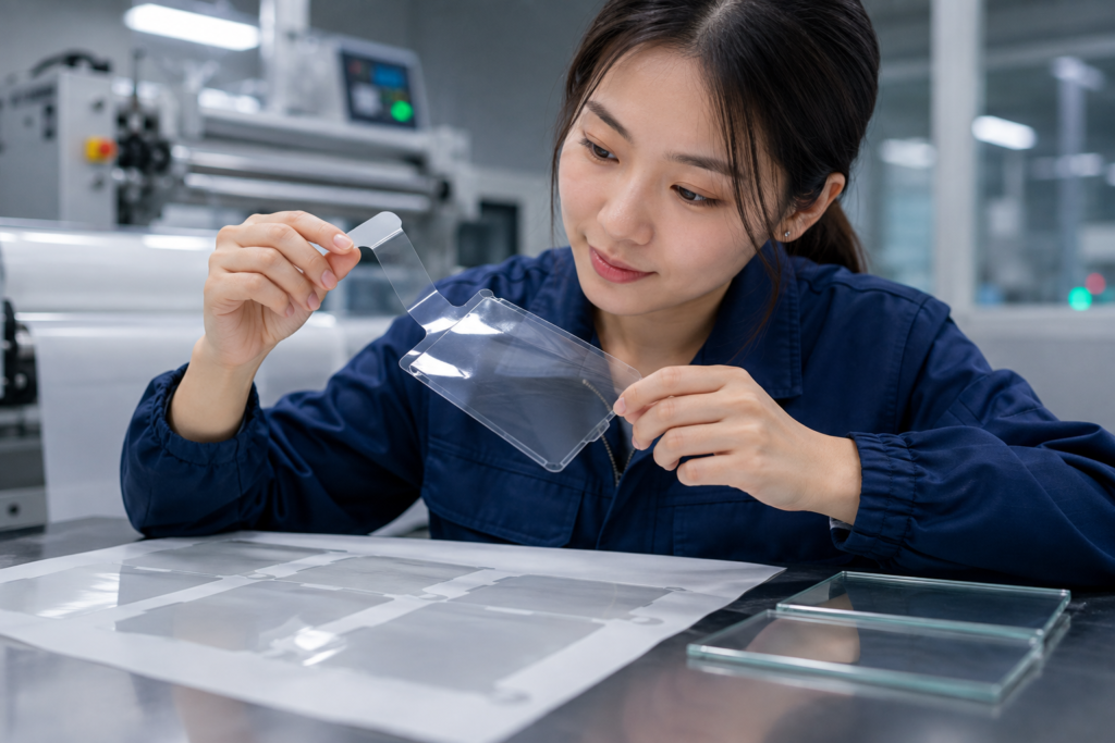
Choosing protective film for optical components requires more than matching film thickness to a drawing. The film must protect the target surface without leaving residue, lifting during handling, trapping contamination or creating removal problems. Engineers should evaluate the protected surface, required adhesion, protection period, environmental exposure and assembly method together. Die-cut geometry, liner design and delivery format also affect production reliability. This guide explains how to evaluate these factors and develop an assembly-ready protective film component for precision optical applications.
Start With the Surface Being Protected
Protective film selection should begin with the actual surface rather than a general film specification.
Optical surfaces may include glass, coated glass, transparent plastic, display cover material or optical windows. Surface finish, coating condition and cleanliness can influence how well the film stays in place and how cleanly it can be removed.
Before selecting a film, confirm:
- What material will contact the adhesive?
- Is the surface smooth, textured, coated or chemically treated?
- Is the film protecting the functional optical area or a surrounding surface?
- Must the surface be inspected while the film remains applied?
- Could application or removal pressure affect the component?
A film that removes cleanly from standard glass may behave differently on coated glass or plastic. Testing on the actual substrate, or a technically representative sample, is more reliable than selecting a film from a general product description.
Key Selection Factors for Protective Film for Optical Components
No single protective film is suitable for every optical application. The following factors should be evaluated as one system.
| Selection factor | What to evaluate | Risk if incorrectly specified |
|---|---|---|
| Protected surface | Material, coating and surface finish | Residue, staining or poor contact |
| Adhesion level | Holding requirement and removal force | Edge lifting or difficult removal |
| Film stability | Flatness, thickness and dimensional behavior | Curling, deformation or misalignment |
| Transparency | Inspection through the applied film | Hidden surface defects |
| Cleanliness | Particles, scratches and handling control | Visible optical contamination |
| Protection period | Assembly, storage and transportation time | Adhesion change or premature lifting |
| Liner design | Release behavior and peeling method | Difficult handling or damaged parts |
| Die-cut geometry | Windows, holes, borders and peel areas | Distortion or waste-removal problems |
| Delivery format | Sheets, rolls or individual pieces | Slow or inconsistent assembly |
The final decision should consider the protective film, adhesive, optional liner, target surface, die-cut profile and customer assembly process together.
Match Adhesion to Protection Time and Handling
Adhesion must be strong enough to prevent movement but controlled enough to allow clean removal.
If adhesion is too low, the film may lift at corners, move during transportation or allow particles to enter beneath the edge. If adhesion is too high, removal may become difficult and the risk of adhesive transfer or surface stress may increase.
“Low tack” should not automatically be interpreted as “residue-free.” Removal performance depends on the adhesive system, protected surface, application pressure, dwell time and environmental exposure.
A practical evaluation should check:
- Initial surface contact;
- Edge condition after handling;
- Adhesion after the intended protection period;
- Removal under the expected production conditions;
- Surface appearance after peeling.
Short room-temperature testing is not enough when the film will remain attached through storage, transport or other production processes.
Control Cleanliness From Converting to Packaging
A transparent film may still be unsuitable for optical use if particles, scratches or adhesive marks are introduced during processing.
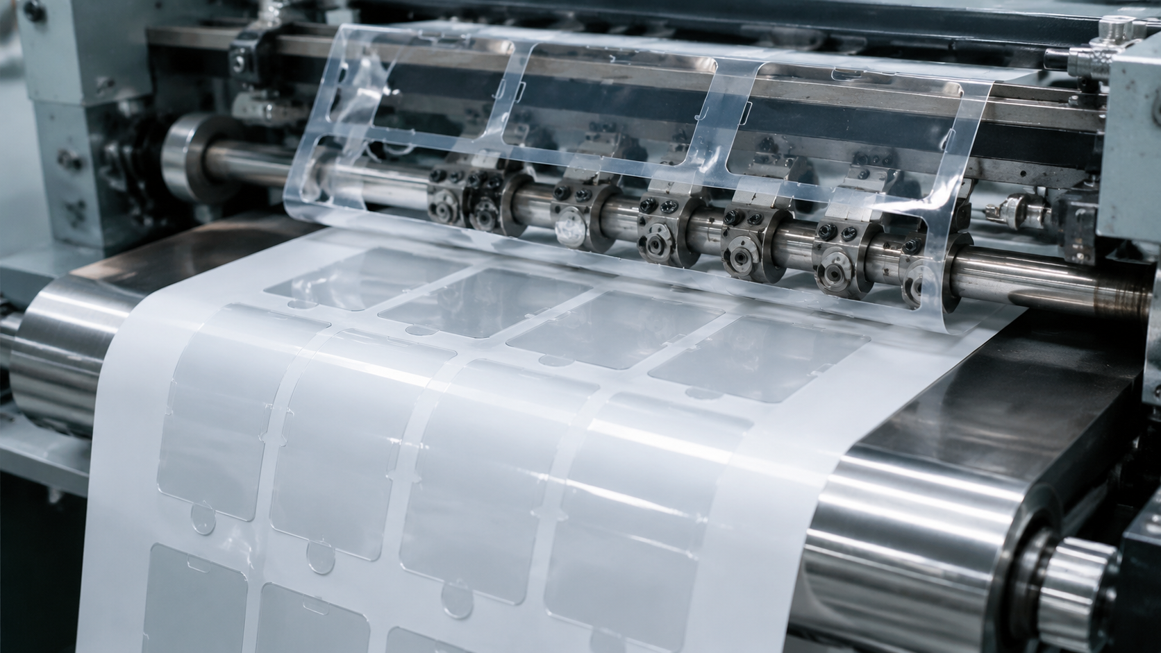
Contamination can occur during unwinding, lamination, slitting, die cutting, waste removal, inspection or packaging. Static charge may also attract particles when the film or liner is separated. Clean raw material alone does not guarantee a clean finished part.
The cleanliness plan should cover:
- Material storage and handling;
- Contact surfaces used during converting;
- Static-control requirements;
- Lamination and cutting conditions;
- Edge and surface inspection;
- Liner protection after die cutting;
- Packaging and transportation.
Sanken’s article on clean production for display film components explains why contamination control must continue across the full converting process.
If operators need to inspect the protected surface through the film, transparency and surface appearance should be confirmed while the film is applied. The customer should define the required optical acceptance criteria because visual requirements differ between applications.
Design the Die-Cut Film for Assembly
Raw film performance is only one part of the decision. The protective film must also be converted into a shape that can be manufactured, peeled and positioned consistently.
Coverage and Edge Position
The profile should cover the required surface without interfering with adjacent components. Insufficient coverage can expose the optical area, while excessive overhang may catch during handling.
Corners and Narrow Sections
Sharp corners and narrow film borders may be more difficult to process and can be vulnerable to deformation or lifting. Geometry should be reviewed against the selected film, adhesive behavior and waste-removal method.
Holes and Windows
Small holes, internal windows and closely spaced features can complicate tooling and waste removal. Finished parts should be checked for incomplete cutting, remaining waste and edge particles.
Non-Adhesive Peel Areas and Extended Liners
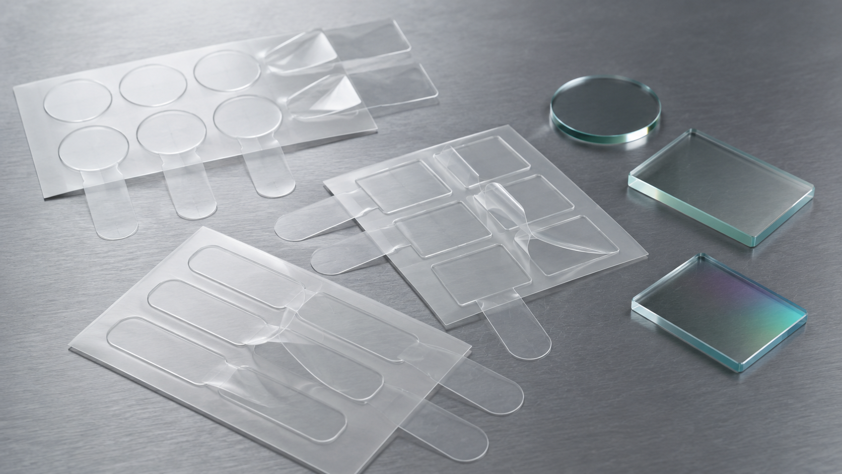
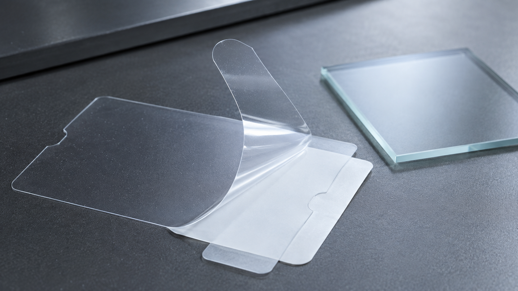
A non-adhesive peel area can be created by leaving part of the protective film edge free from adhesive contact. An extended release liner may also provide an accessible edge that helps operators separate the film from its carrier.
These features can reduce direct contact with the protected surface and make manual removal easier. Their position, size and peeling direction should match the available access space and customer assembly sequence.
The exact structure must be confirmed through the customer drawing, approved material and sample evaluation. It should not be treated as a standard feature for every protective film application.
Kiss-Cut Depth
For protective film supplied on a carrier liner, kiss cutting should separate the part while keeping the liner functional. Cutting too deeply can damage the liner; cutting too shallowly can make the part difficult to remove.
Sanken processes custom die-cut film components using approved material structures and customer drawings. Design review before tooling helps identify features that may affect cutting, peeling or waste removal.
Select a Delivery Format for the Assembly Process
Delivery format affects handling, orientation and contamination risk.
Sheets are often practical for prototypes, pilot production and manual assembly. Roll formats may support repeated or automated placement when part pitch, winding direction and liner behavior match the customer’s equipment. Individual pieces may be suitable for lower-volume projects or special packaging requirements.
Before sampling, confirm:
- Manual or automated application;
- Part orientation and peeling direction;
- Sheet layout or roll configuration;
- Part pitch and spacing;
- Extended liner requirements;
- Packaging and cleanliness requirements.
The guide to die-cut parts supplied in sheets, rolls or kits provides a more detailed comparison of production delivery formats.
Validate the Finished Die-Cut Component
A raw-material data sheet cannot confirm how the finished part will perform in the customer’s process. Sampling should evaluate the complete converted structure under representative conditions.
The validation plan may include:
- Fit against the drawing or application sample;
- Surface appearance before and after application;
- Edge condition after handling and storage;
- Removal after the required dwell time;
- Residue or visible surface change after peeling;
- Extended peel area or liner usability;
- Dimensional stability and part flatness;
- Compatibility with the intended placement method.
Acceptance requirements should be agreed through drawings, samples and customer specifications. Adhesion, tolerance and cleanliness values should not be copied from a different optical application without validation.
For structured or particularly sensitive optical films, What Protection Works for Die-Cut Brightening Film Parts? provides additional guidance on liners, contamination and surface damage.
How Sanken Supports Optical Protective Film Projects
Sanken converts approved protective films into custom parts for optical, display and electronic assembly applications. Relevant capabilities include laminating, slitting, rewinding, precision die cutting, kiss cutting, through cutting, waste removal, dimensional inspection, visual inspection and production packaging.
Depending on the approved drawing and material structure, protective film parts can incorporate custom profiles, windows, holes, non-adhesive peel areas or extended release liners. They can also be supplied in sheets, rolls or other agreed formats according to the customer’s assembly process.
These structures are not fixed products. Their feasibility must be confirmed according to the selected protective film, adhesive coverage, liner design, part geometry and customer application method.
More information is available on Sanken’s optical and display component page and custom optical protective film page.
Information Needed Before Sampling
For a more effective evaluation, provide:
- Drawing or physical sample;
- Target surface and required protection area;
- Approved material or film requirement;
- Thickness and tolerance;
- Adhesion and removal requirements;
- Protection period and storage conditions;
- Assembly and peeling method;
- Extended peel area or liner requirements;
- Annual volume;
- Preferred delivery and packaging format.
If the material has not been approved, testing should begin with the actual surface and production sequence rather than a generic film recommendation.
Conclusion
The right protective film for precision optical applications must protect the surface while remaining compatible with converting, handling, inspection and removal. Surface type, adhesion, dwell time, cleanliness, geometry, liner design and delivery format should be evaluated as one system.
If you are evaluating a custom die-cut protective film, send Sanken your drawing, target surface, material requirement, thickness, tolerance, protection period, assembly method, annual volume and preferred delivery format. The team can review the structure and manufacturing feasibility before sampling.