

Camera module light leakage can often be reduced by placing a precisely shaped, opaque gasket around the optical window or another defined interface in the module assembly. The gasket helps close unintended light paths, mask non-imaging areas and maintain controlled contact between adjacent parts. However, successful light blocking depends on more than using a black material. Engineers must also consider aperture accuracy, gasket width, thickness, compression, adhesive behavior, cut-edge quality and assembly alignment. This article explains how to evaluate these factors before tooling and production.
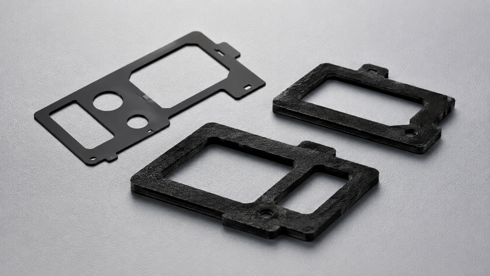
Where Light Leakage Can Occur
A camera module contains several closely positioned optical and structural elements. If an unintended gap remains around an optical window, sensor area or housing interface, external or internally reflected light may reach an area where it is not wanted.
Possible causes include:
- An oversized or incorrectly positioned gasket aperture
- Insufficient contact between the gasket and adjoining surfaces
- Uneven gaps caused by housing variation
- Gasket movement during bonding
- Foam compression that is too low or inconsistent
- Narrow gasket walls that deform during peeling or placement
- Adhesive overflow extending into the optical opening
- Burrs, particles or damaged edges near the light path
A die-cut gasket cannot correct every optical design problem. It must work together with the housing geometry, optical path and assembly stack-up. Prototype testing in the actual module structure remains necessary.
How a Die-Cut Gasket Controls Unwanted Light
A light-blocking gasket normally forms a defined barrier around an aperture or between two mating surfaces. Depending on the construction, it may perform one or more functions:
- Masking the area outside the intended optical opening
- Closing small structural gaps
- Providing controlled compression between surfaces
- Positioning or bonding adjacent components
- Supporting dust protection around the interface
- Reducing unwanted reflections from exposed internal surfaces
The gasket’s inner opening is particularly important. If it is too large, an unwanted light path may remain. If it is too small or misaligned, the gasket could interfere with the intended optical area.
This is why a camera module light-blocking gasket should be treated as a precision component rather than a simple black pad.
Selecting the Appropriate Gasket Structure
Sanken can convert confirmed materials such as black PET film, foam, rubber and adhesive tape into custom components. The correct direction depends on the interface and the problem that must be controlled.
| Structure | Main Advantage | Important Limitation |
|---|---|---|
| Black PET film | Thin profile and dimensional stability | Does not compensate for large or uneven gaps |
| Black foam | Conformability and controlled gap filling | Compression and recovery must be validated |
| Adhesive-backed black PET | Thin light barrier with positioning support | Adhesive must match the bonding surface |
| Adhesive-backed foam | Light blocking, gap filling and easier placement | Total thickness and adhesive flow require control |
| Rubber gasket | Compression and sealing support | Hardness and assembly load must suit the structure |
| Film, foam and adhesive laminate | Combines stability, cushioning and bonding | Layer alignment and total stack-up become more complex |
Black PET is often the better starting point when space is limited and the design requires a thin, stable frame. Foam may be more suitable when the interface includes a variable gap that requires compression. Depending on the application, Sanken can process EVA, PE, PU, EPDM or silicone foam, but the final choice must be confirmed against the drawing and operating conditions.
The material’s color alone does not prove that it will provide sufficient light blocking. Opacity, surface appearance, thickness and performance under the intended light source should be verified using the customer’s test method.
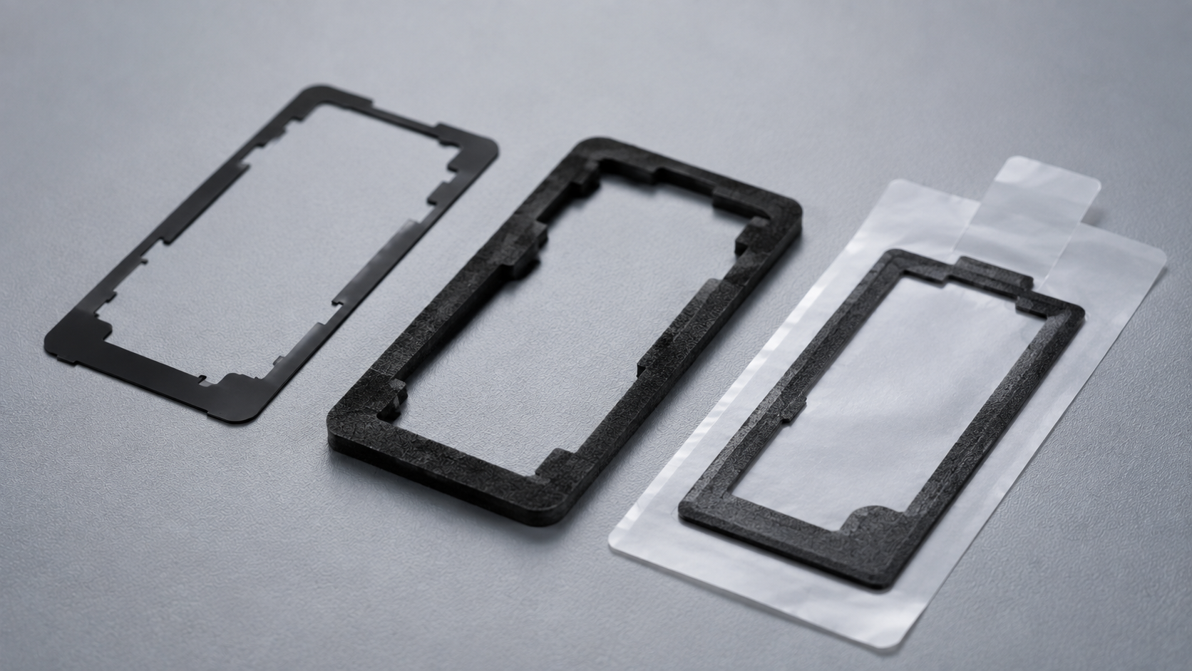
Control the Aperture and Gasket Width
The inner aperture should be designed from the functional optical opening, assembly tolerance and permitted positional variation. The drawing should clearly identify the dimensions that directly affect the light path.
Critical features may include:
- Inner aperture length and width
- Aperture position relative to the outer profile
- Minimum gasket wall width
- Corner radius
- Locating holes or notches
- Distance between the aperture and adhesive edge
- Orientation features for assembly
Very narrow borders may stretch during liner removal, distort during waste stripping or shift during placement. Sharp internal corners can also make thin or soft gasket structures more difficult to convert.
Before tooling, the drawing should be reviewed for both optical clearance and die-cut manufacturability. Sanken’s precision die-cutting services include drawing review, material converting, laminating, kiss cutting, through cutting and inspection support.
Match Thickness and Compression to the Assembly Gap
For a film gasket, the total thickness must fit the available stack-up without introducing interference.
For a foam or rubber gasket, engineers should also consider compression. Too little compression may leave a light path. Excessive compression may deform the gasket, increase assembly load or push material toward the aperture.
The evaluation should include:
- Nominal interface gap
- Maximum and minimum gap after tolerance accumulation
- Uncompressed gasket thickness
- Expected compression during assembly
- Material recovery after compression
- Adhesive thickness, when used
- Performance after relevant environmental exposure
Sanken should not specify a universal compression percentage without the selected material data and customer test conditions. The required value depends on foam type, density, thickness, housing rigidity and application environment.
Evaluate the Adhesive as Part of the Gasket
When a gasket requires adhesive backing, the adhesive should be selected according to the actual bonding surfaces and assembly conditions. A tape that bonds well to one plastic or coated surface may behave differently on another.
Important questions include:
- What materials form the two mating surfaces?
- Is the surface flat, textured or curved?
- Is initial tack important for placement?
- Will the assembly experience heat or humidity?
- Can adhesive overflow enter the aperture?
- Must the liner support manual or automated placement?
- Will repositioning be required during assembly?
Adhesive should be included in the total stack-up, not treated as a separate accessory. The relationship between the carrier, adhesive and release liner affects bonding, die cutting, waste removal and placement.
For additional selection considerations, see How Double-Sided Tape Works for Die-Cut OEM Parts.
Prevent Deformation During Peeling and Placement
Small frame-shaped gaskets can be difficult to handle. Narrow walls may stretch, fold or twist when removed from the release liner.
Possible design improvements include:
- Selecting a liner with appropriate release behavior
- Increasing border width where the assembly permits
- Adding a liner extension outside the finished gasket
- Maintaining the part on a carrier for placement
- Supplying parts at controlled spacing on sheets or rolls
- Adding an orientation feature to reduce placement errors
The correct delivery format depends on production volume and the customer’s assembly method. Sanken can provide liner-supported components in sheets, rolls or application-specific kits. The differences are explained in Die-Cut Parts in Sheets, Rolls, or Kits.
Die-Cutting Quality Affects Optical Performance
Even when the correct material is selected, poor converting can compromise the gasket.
Common risks include:
- Inaccurate inner apertures
- Film burrs or deformed edges
- Crushed foam cells
- Adhesive overflow
- Incomplete cutting
- Release-liner damage
- Difficult waste removal
- Layer misalignment in laminated structures
- Particles remaining on the finished component
Depending on the construction, the process may require laminating, slitting, kiss cutting, through cutting and controlled waste removal. Kiss cutting is useful when the finished gasket must remain on a release liner, but the cutting depth must separate the part cleanly without damaging the carrier.
Sanken’s optical and display component manufacturing supports custom black film, foam, adhesive tape and composite light-blocking parts for camera modules, sensor areas and optical windows.
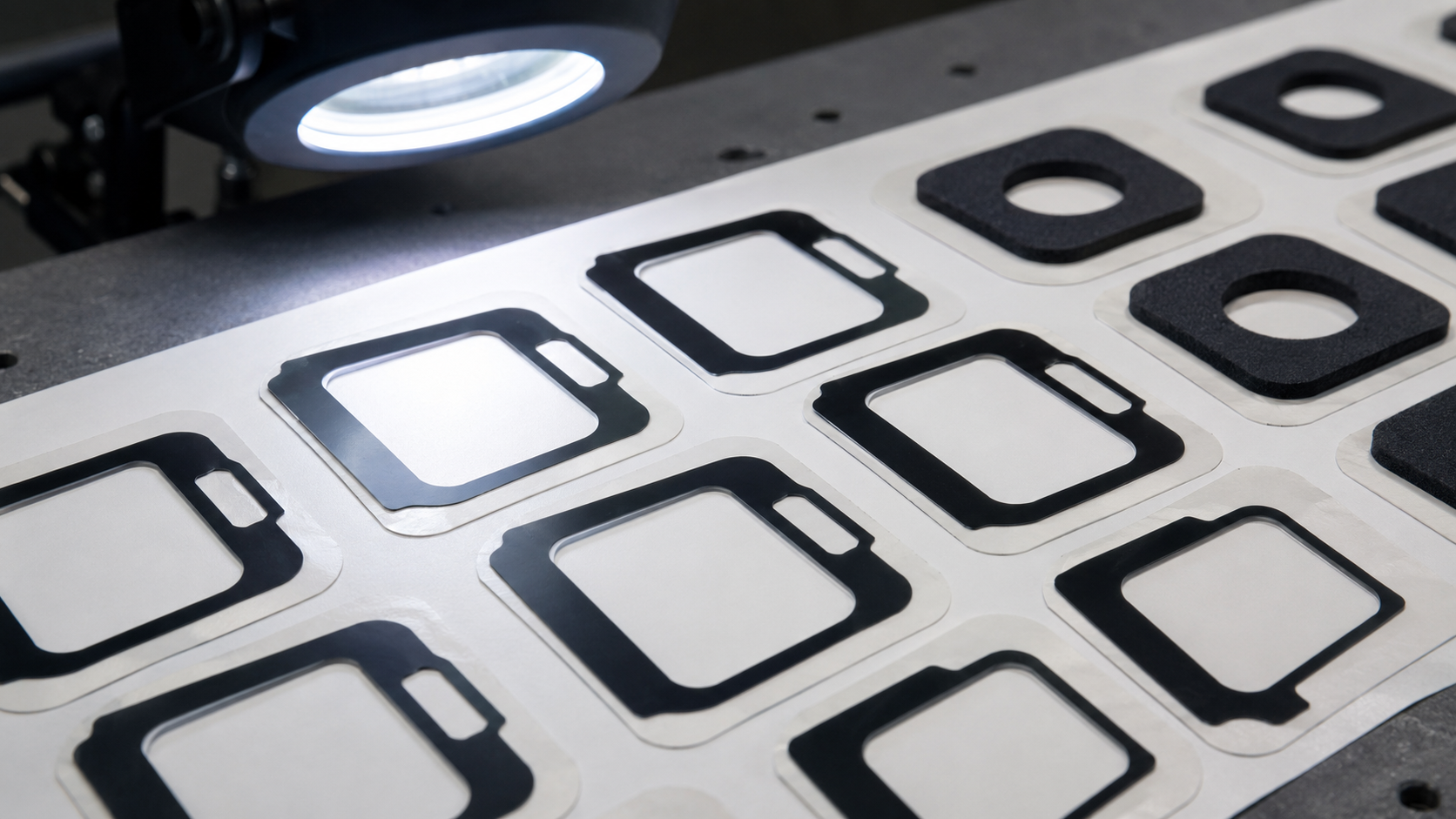
Inspection Points Before Mass Production
Inspection should focus on characteristics that influence fit, handling and light blocking.
Recommended checkpoints include:
- Material and total thickness
- Inner and outer dimensions
- Aperture position
- Minimum wall width
- Part flatness
- Cut-edge condition
- Adhesive position and overflow
- Liner integrity
- Peeling and placement behavior
- Packaging condition
Dimensional inspection alone cannot confirm optical performance. The customer should also test prototypes in the intended assembly under relevant lighting angles and operating conditions.
If leakage remains, the review should identify whether it comes from the gasket aperture, compression, material transmission, another structural gap or internal reflection. This prevents repeated material changes that do not address the actual failure mechanism.
Information Needed for a Gasket Evaluation
To evaluate a custom camera module light-blocking gasket, provide:
- Two-dimensional drawing with critical dimensions
- Application position or interface drawing
- Required material or functional description
- Nominal thickness and tolerance
- Mating surface materials
- Assembly gap and expected compression
- Adhesive and release-liner requirements
- Manual or automated placement method
- Prototype and annual volume
- Preferred sheet, roll or kit format
- Customer light-leakage test requirements
- Packaging and cleanliness requirements
Sanken can then review the proposed structure for material compatibility, aperture design, die-cut feasibility, waste removal, inspection and delivery format. Final suitability should be confirmed through samples and testing in the customer’s real assembly.
Conclusion
Die-cut gaskets can reduce camera module light leakage when the material, aperture, thickness, compression and adhesive structure are designed as one system. Black PET provides a thin and dimensionally stable barrier, while black foam or rubber can accommodate interfaces that require controlled compression. Accurate die cutting, clean edges, stable liner release and assembly-friendly packaging are equally important.
If you are evaluating a custom camera module light-blocking gasket, send Sanken your drawing, application position, material requirement, thickness, tolerance, bonding surface, expected volume and preferred delivery format. Our team can review the structure and manufacturing feasibility before sampling.
Related Articles
- Which Custom Die-Cut Spacers Prevent Sensor Lens Offset During Assembly?
- How Double-Sided Tape Works for Die-Cut OEM Parts
- Why Is PET Film Commonly Used in Electronics?
- What Die-Cut Films, Foams, and Adhesive Parts Are Used in Electronic Products?
- Why Do Display Film Components Require Clean Room Production?
- Die-Cut Parts in Sheets, Rolls, or Kits: How to Choose the Right Format