
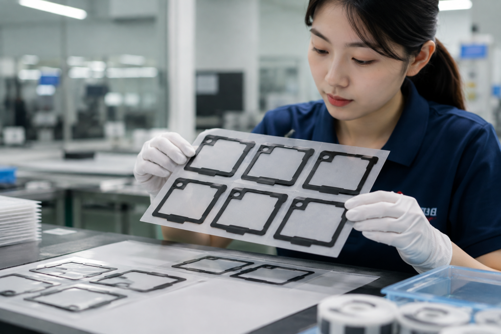
Adhesive bleed occurs when adhesive moves beyond the intended edge of a die-cut component. In camera module assembly, this can contaminate nearby surfaces, obstruct small openings, complicate part removal and reduce placement accuracy.
The cause depends on when the defect appears. Bleed observed immediately after cutting may indicate excessive processing pressure, while bleed discovered after transportation may relate to packaging compression or insufficient liner support.
Identifying the stage at which the problem develops helps engineers evaluate the adhesive construction, component geometry, converting process and delivery format more effectively.
Why Adhesive Bleed Matters in Camera Module Applications
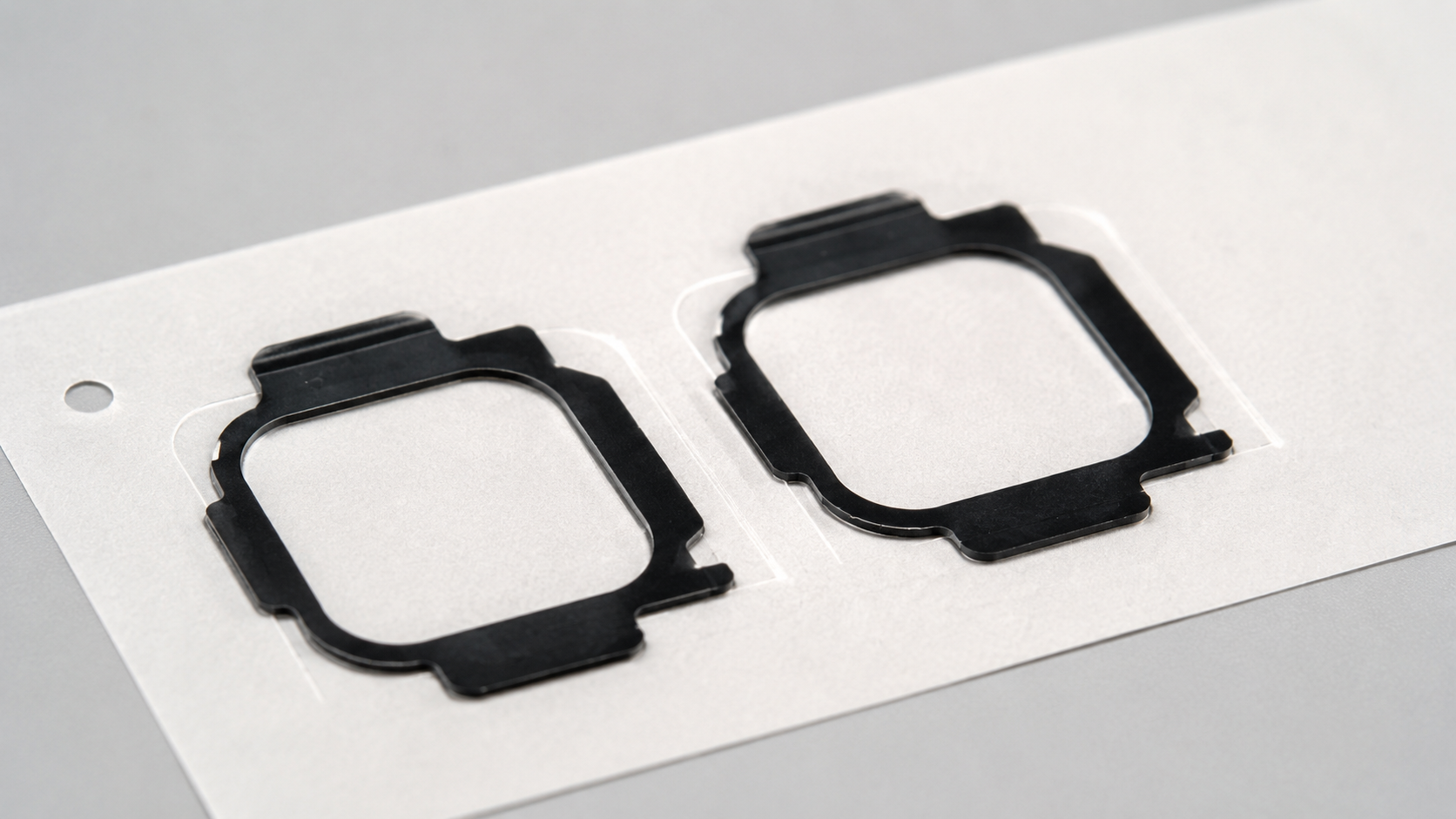
Die-cut adhesive components may be used around small openings, between structural bonding surfaces or near light-blocking parts in camera module assemblies.
These locations often provide limited space for adhesive movement. Material extending beyond the intended boundary can create several manufacturing problems:
- Contamination near sensitive optical areas.
- Partial obstruction of small component openings.
- Adhesive transfer to adjacent parts.
- Difficulty removing components from the release liner.
- Distortion during manual or automated placement.
- Additional inspection and assembly rework.
The risk depends on the actual part location, available clearance and customer assembly process. Reviewing the intended optical component application helps determine which component edges require the closest control.
Determine When the Adhesive Bleed First Appears
The first engineering question should be when the defect becomes visible.
| When the problem appears | Likely ahttps://sankenprecision.com/wp-content/uploads/2026/08/chatgpt-image-2026年8月24日-11_58_20.pngreas to investigate |
|---|---|
| Immediately after die cutting | Cutting pressure, tool condition and adhesive construction. |
| During waste removal | Narrow borders, internal openings and stripping method. |
| When removing the part from its liner | Liner release behavior and component support. |
| After storage or transportation | Stacking pressure, packaging and storage conditions. |
| After final placement | Assembly pressure, bonding surface and available edge clearance. |
These observations do not establish a definitive cause by themselves, but they help narrow the investigation before changing the material or component design.
How Material Construction Influences Edge Stability
A die-cut adhesive component should be evaluated as a complete material stack rather than as adhesive alone.
Depending on the application, the structure may include an adhesive layer, a PET carrier, a release liner or an adhesive-backed foam component.
Important considerations include:
- Adhesive thickness relative to part geometry.
- Internal adhesive strength and tendency to deform under pressure.
- Whether a carrier provides adequate structural support.
- Compatibility between the adhesive and release liner.
- Clearance between exposed adhesive edges and nearby features.
For example, a PET-supported adhesive structure may offer better dimensional support than an unsupported construction in certain narrow designs. However, the actual result depends on the adhesive system, part geometry and manufacturing process.
Understanding different double-sided tape structures helps engineers determine which construction should be evaluated during sampling.
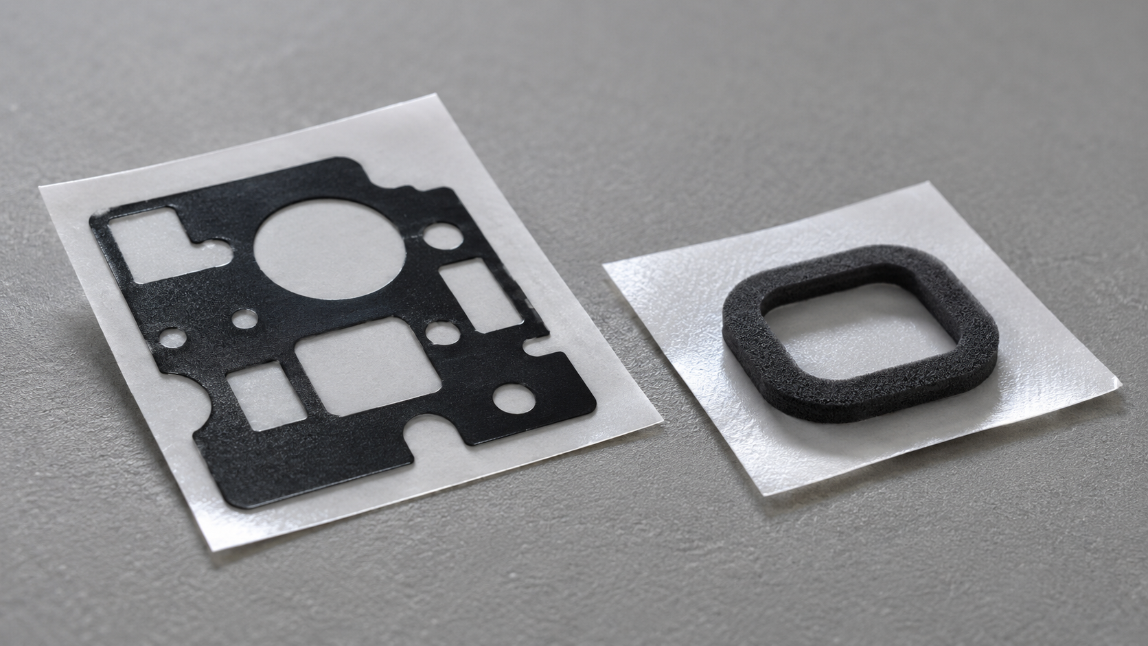
Image description: Side-angle macro view of one thin black PET-backed adhesive die-cut component and one small adhesive-backed foam gasket, naturally positioned on separate release liners. Emphasize realistic material layers, clean edges and practical component geometry. No complete camera modules, electronic devices, people, text, labels, logos or arrows. File size: 100–200 KB. Width: 1600–1920 px.
Review Cutting Pressure and Component Geometry
When adhesive bleed appears immediately after manufacturing, the converting process deserves close attention.
Excessive lamination pressure can compress adhesive toward the outer edge before cutting. Unsuitable cutting pressure or tool condition can further deform the material around the component perimeter.
Narrow borders and small internal openings may increase sensitivity because less surrounding material is available to support the adhesive structure.
Practical design and manufacturing questions include:
- Are the narrowest sections appropriate for the selected material structure?
- Does the drawing provide enough clearance around critical openings?
- Is the cutting method suitable for the adhesive and liner combination?
- Could lamination pressure be contributing to edge deformation?
- Does the tooling produce stable component edges?
- Can the waste material be removed without pulling adhesive into the opening?
A precision die-cutting process review should consider the complete stack-up, cutting approach and downstream handling requirements.
Check Release Liner Performance and Waste Removal
Some components leave the cutting process with clean edges but develop defects during waste removal or liner separation.
A narrow adhesive section may stretch when surrounding waste is removed. Similarly, an unsuitable release liner can make the component difficult to lift without disturbing its shape.
Engineers should evaluate whether the liner provides sufficient support for the part geometry and whether release behavior suits the intended assembly method.
If an adhesive-backed foam component is involved, compression and edge support should also be considered during foam gasket material selection.
The objective is not simply easy release. The component must remain stable throughout processing, packaging and placement.
Inspect Packaging and Delivery Conditions
If components appear acceptable after manufacturing but show adhesive transfer later, investigate how they are stored and delivered.
Potential contributing factors include:
- Excessive pressure from stacked sheets.
- Compression inside packaging.
- Insufficient separation between components.
- Delivery formats that leave narrow parts unsupported.
- Handling conditions that distort the release liner.
Selecting suitable sheet, roll or kit delivery formats can help reduce unnecessary movement and support more consistent component handling.
Packaging decisions should be verified against the actual transportation, storage and assembly conditions rather than based on general assumptions.
Information Engineers Should Provide Before Sampling
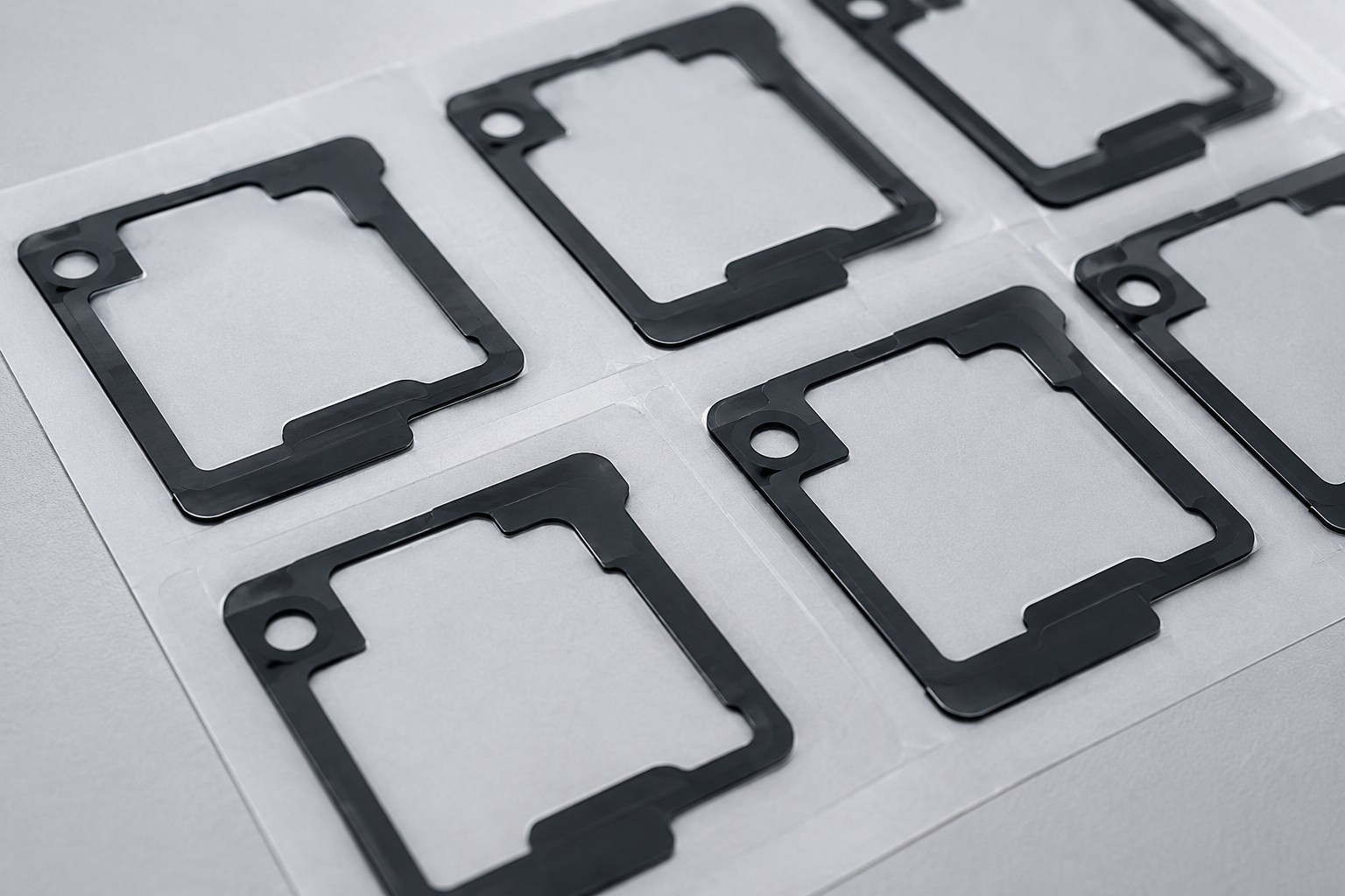
A useful sampling review requires more than the outline dimensions of the component.
Provide:
- Part drawing and critical internal openings.
- Application position and adjacent sensitive areas.
- Bonding surface and expected assembly method.
- Preferred adhesive construction or available material specifications.
- Overall thickness and proposed material layers.
- Areas where adhesive exposure is unacceptable.
- Liner and delivery format requirements.
- Expected production volume.
- Relevant storage, transportation and handling conditions.
These details help identify whether the proposed component can be manufactured and delivered in a form suitable for the intended application.
Additional custom adhesive component quotation requirements can support a more effective engineering review.
Conclusion
Adhesive bleed in camera module die-cut parts is rarely explained by material selection alone. Reliable evaluation requires identifying when the defect appears and reviewing the relationship between adhesive construction, component geometry, cutting pressure, liner support and packaging.
If you are evaluating a custom die-cut adhesive component, send Sanken your drawing, material requirements, bonding surface, thickness, annual volume and preferred delivery format for a manufacturing feasibility review.
Related Articles
- How Double-Sided Tape Works for Die-Cut OEM Parts
- How to Choose Adhesive-Backed Foam Gaskets for OEM Assembly
- How Die-Cut Parts Are Supplied in Sheets, Rolls, or Kits
- What Information Should You Provide for a Custom Adhesive Tape Die-Cut Part Quotation?
- Which Custom Die-Cut Spacers Prevent Sensor Lens Offset During Assembly?
- Why Is PET Film Commonly Used in Electronics?