

Light-blocking gaskets for optical sensors help reduce unwanted light entering through gaps around a sensor window, lens opening or adjacent light source. Effective performance depends on more than using a black material. Engineers must review the gasket’s inner opening, coverage, thickness, compression, adhesive structure, edge quality and assembly position. A gasket that looks correct before installation may still leak light if it shifts, leaves a local gap or interferes with the intended optical path. The following seven checks provide a practical starting point for evaluating a custom die-cut structure.
Why Optical Sensor Assemblies Develop Light Leakage
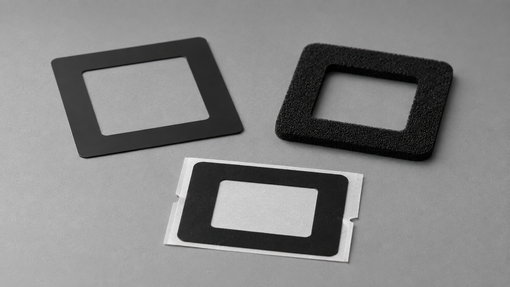
Light leakage occurs when unwanted light reaches a sensor through a path that should be blocked. The path may be created by a gap around the optical window, an undersized gasket, incorrect placement, insufficient foam compression or a distorted adhesive frame.
The result depends on the optical design. Unwanted light may contribute to:
- Stray-light interference
- Uneven illumination
- Reduced signal stability
- Bright spots or unwanted reflections
- Inconsistent sensor readings
- Optical inspection failures
- Rework during assembly
A light-blocking gasket does not correct the optical design itself. Its role is to create a controlled barrier around the required opening while maintaining the intended clear aperture.
Sanken converts black PET film, black foam and adhesive tape into custom light-blocking frames through precision die cutting, lamination, kiss cutting, through cutting, waste removal, inspection and packaging. The final material and geometry must be verified using the customer’s drawing and actual optical test conditions.
Design Check 1: Identify the Exact Leakage Path
Before choosing a material, engineers should determine where the unwanted light is entering.
Potential leakage paths include:
- The gap between a sensor window and its surrounding structure
- Corners that are not fully covered
- Openings created by tolerance stack-up
- A space between two rigid surfaces
- An adhesive frame that has shifted
- A foam gasket that is not compressed evenly
- An internal cutout that is too large
- A narrow area where the gasket has stretched or torn
The gasket should be designed around the actual leakage path rather than around the general outline of the component.
A useful review begins with three questions:
- Where is the unwanted light source?
- Which path allows that light to reach the sensor?
- Which surfaces can support a stable light-blocking component?
This prevents the project from selecting a black film or foam before its real function is understood.
Design Check 2: Choose the Appropriate Gasket Structure
Different light-blocking materials solve different mechanical problems. Color alone is not enough.
| Component structure | Suitable design direction | Main limitation to review |
|---|---|---|
| Black PET film frame | Thin, dimensionally stable light-blocking coverage | Limited gap compensation |
| Black adhesive tape frame | Light blocking combined with bonding or positioning | Adhesive compatibility and lifting |
| Black foam gasket | Gap filling, cushioning and controlled compression | Compression and thickness stability |
| Adhesive-backed black foam | Gap control with easier placement | Total thickness and adhesive position |
| Laminated film-and-adhesive frame | Stable handling and controlled bonding area | Layer alignment and edge condition |
Black PET film may be suitable where the assembly needs a thin, stable frame with an accurate inner window. Black foam may be more appropriate when the gasket must conform to a controlled gap. A black adhesive tape frame can combine positioning, bonding and light-blocking functions.
However, a material’s black appearance does not automatically confirm its optical performance. Opacity, reflection behavior and suitability for the relevant light source should be confirmed through material documentation and application testing.
For more information on available structures, review die-cut light-blocking films for optical and electronic components.
Design Check 3: Control the Inner Window and Coverage Area
The inner opening is one of the most important dimensions in a light-blocking gasket.
If the opening is too large, it may expose a leakage path. If it is too small or incorrectly positioned, the gasket may interfere with the required optical area.
Engineers should define:
- Inner opening dimensions
- Inner opening position
- Required clear aperture
- Distance from the gasket edge to the optical path
- Minimum coverage around corners
- Relationship between the inner and outer profiles
- Locations where adhesive or foam must not enter
- Orientation features used during assembly
The drawing should distinguish between functional optical dimensions and noncritical handling areas. This helps focus manufacturing and inspection controls on the features that affect performance.
Narrow walls around the opening also require attention. They may stretch during liner peeling, move during waste removal or deform during assembly. Rounded internal corners and practical wall widths can improve part stability, depending on the available design space.
Design Check 4: Match Thickness and Compression to the Gap
A thin film and a compressible foam gasket behave differently after assembly.
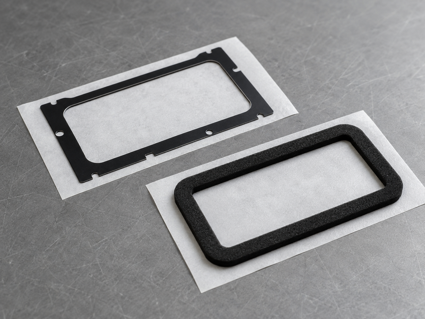
Black PET film provides little gap compensation. If two surfaces are uneven or separated by a variable gap, the film may not close the complete leakage path.
Foam can conform to a gap, but its performance depends on controlled compression. Insufficient compression may leave local openings. Excessive compression may deform the gasket, increase assembly stress or push material toward the optical window.
For foam gasket designs, review:
- Nominal material thickness
- Actual assembly gap
- Expected compression
- Compression distribution
- Surface flatness
- Gasket wall width
- Long-term compressed condition
- Total thickness after adhesive lamination
The correct structure should maintain contact around the complete sealing path without obstructing the optical opening.
Thickness should be evaluated as part of the full stack-up. For an adhesive-backed foam gasket, the structure includes the foam, adhesive and any carrier layers—not only the foam itself.
Design Check 5: Review Adhesive Position and Liner Design
Adhesive can simplify assembly by holding a light-blocking gasket in position. It can also create defects when poorly designed.
Potential risks include:
- Adhesive extending into the optical opening
- Adhesive overflow at narrow edges
- Gasket movement after placement
- Edge lifting
- Uneven adhesive thickness
- Difficult liner removal
- Part distortion during peeling
- Contamination from exposed adhesive
The adhesive should match the bonding surface, which may be PET, glass, coated material, molded plastic or metal. The final selection must be validated on the actual production surface.
Liner design also affects positioning. A stable release liner can keep narrow gasket sections organized until placement. Extended liner edges, split liners or pull tabs may make peeling easier, but their location should not stretch fragile sections.
When designing an adhesive-backed light-blocking gasket, review the full structure:
Light-blocking material + adhesive layer + release liner + bonding surface + assembly method
The part should be evaluated as an assembly-ready component, not as an isolated material.
Design Check 6: Prevent Edge Defects and Contamination
Optical applications require clean edges because cutting debris, foam particles or adhesive residue can move toward the sensor window.
Possible manufacturing risks include:
- Film burrs
- Torn foam cells
- Adhesive strings
- Incomplete internal waste removal
- Distorted narrow sections
- Scratched film surfaces
- Dust trapped on adhesive
- Loose particles inside the gasket opening
Tooling, cutting pressure and waste-removal direction should be selected according to the material structure. A black PET frame may require different process control from a soft foam gasket or multilayer adhesive component.
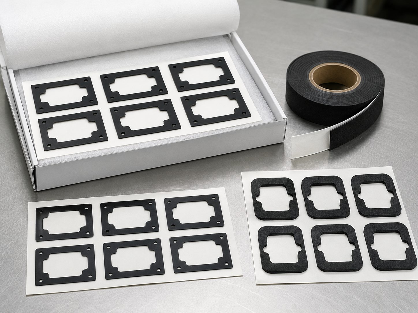
Kiss cutting can keep adhesive-backed parts organized on the liner, while through cutting may be suitable for individually supplied components. The best method depends on geometry, material behavior and assembly format.
Clean handling must continue after cutting. Inspection and packaging should protect the finished gasket from dust, deformation and liner damage before customer assembly. These controls are particularly important for optical and display die-cut components.
Design Check 7: Validate the Gasket in the Actual Assembly
A light-blocking gasket cannot be approved only by measuring its outer dimensions.
The prototype should be installed in a representative assembly and evaluated under the relevant light source, viewing direction and mechanical conditions.
Validation may need to review:
- Visible leakage around the complete perimeter
- Gasket alignment with the optical opening
- Coverage at corners and narrow sections
- Compression after assembly
- Adhesive lifting or movement
- Interference with the clear aperture
- Particle or adhesive contamination
- Performance after relevant environmental exposure
- Repeatability across multiple samples
The customer should define the light-leakage test method and acceptance criteria. Without a confirmed test setup, the supplier should not claim a specific light-blocking result.
Testing should also consider tolerance stack-up. A gasket may work in the nominal assembly but leave a gap when component dimensions move within their permitted ranges.
For related alignment considerations, see Which Custom Die-Cut Spacers Prevent Sensor Lens Offset During Assembly?.
How Sanken Supports Light-Blocking Gasket Projects
Sanken supports custom light-blocking components made from confirmed materials such as black PET film, black foam and adhesive tape.
Depending on the drawing and assembly method, manufacturing support may include:
- Material and structure review
- Adhesive lamination
- Slitting and rewinding
- Precision inner-window die cutting
- Kiss cutting or through cutting
- Waste removal
- Dimensional and visual inspection
- Sheet, roll or kit supply
- Protective packaging
Sanken does not manufacture complete optical sensors or camera modules. Our role is to convert suitable flexible materials into custom components that match the customer’s drawing and assembly process.
For a broader overview of black film converting, review custom die-cut black light-blocking films for OEM electronics.
Conclusion
Light-blocking gaskets for optical sensors must control the actual leakage path without interfering with the intended optical opening. Reliable performance depends on material structure, inner-window accuracy, coverage, thickness, foam compression, adhesive position, edge cleanliness and assembly validation.
If you are evaluating a black PET film frame, black foam gasket or adhesive light-blocking component, send Sanken your drawing, material requirement, thickness, bonding surface, application gap, annual volume and preferred delivery format. Our team can review the converting and manufacturing feasibility before sampling.
Related Articles
Die-Cut Light-Blocking Films for Optical and Electronic Components
Custom Die-Cut Black Light-Blocking Films for OEM Electronics
Which Custom Die-Cut Spacers Prevent Sensor Lens Offset During Assembly?
How Precision Die-Cutting Helps Protect Sensors, Cameras, and Display Modules
How to Choose Die-Cut Films and Adhesive Materials for Display Module Assembly