
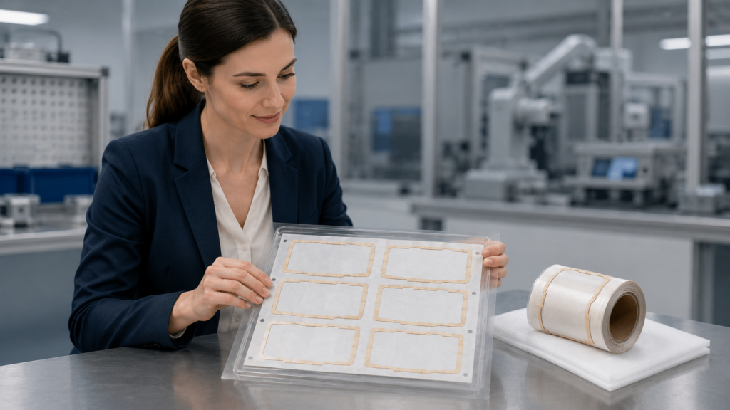
Die-cut adhesive tape can help prevent edge lifting in display module assembly when the adhesive, bonding surface, tape thickness, part geometry and liner design are evaluated together. A precisely converted tape frame provides controlled coverage around the display perimeter and reduces the variation associated with manually cut or positioned tape. However, die-cutting accuracy alone cannot guarantee reliable bonding. Engineers must also consider surface cleanliness, narrow-border stress, assembly pressure, packaging and the conditions the bonded component will face after assembly.
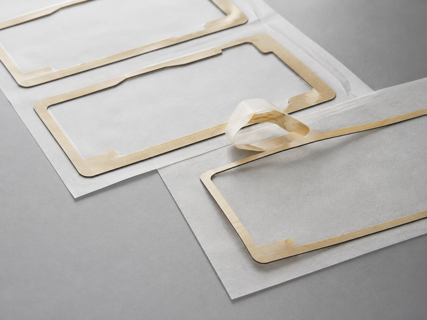
What Die-Cut Adhesive Tape Does in Display Modules
In this application, die-cut adhesive tape normally refers to a custom double-sided tape frame, PET-backed adhesive part or foam tape component used around the perimeter of a display assembly. It is not necessarily the transparent adhesive used for full-surface optical lamination.
A typical peripheral bonding structure may include:
- A display panel, cover or flat component
- A die-cut double-sided adhesive frame
- A plastic or metal supporting housing
The adhesive frame follows the required bonding path while leaving the active display area open. Depending on the design, it may also include openings for sensors, connectors or other functional areas.
These parts can support:
- Peripheral display bonding
- Component positioning
- Controlled spacing
- Local dust protection
- Cushioning between rigid surfaces
- Light control when an approved black adhesive structure is used
- Faster and more repeatable assembly
Sanken converts adhesive tapes and related flexible materials into custom parts through precision die cutting, lamination, slitting, kiss cutting, waste removal, inspection and packaging. The tape material and finished structure must still be confirmed according to the customer’s drawing and application requirements.
Why Edge Lifting Happens in Display Module Bonding
Edge lifting occurs when part of the adhesive frame loses contact with the bonding surface. It may appear immediately after application or later during handling, storage or end-use exposure.
The defect rarely has only one cause. It normally results from an interaction between the tape, part design and assembly process.
| Risk factor | Possible effect |
|---|---|
| Incompatible adhesive and substrate | Poor wet-out or weak bonding |
| Dust, oil or release-agent residue | Local loss of adhesion |
| Narrow or sharply angled frame geometry | Higher stress at edges and corners |
| Tape thickness unsuitable for the surface gap | Incomplete surface contact |
| Excessive liner release force | Stretching or distortion during peeling |
| Uneven assembly pressure | Unbonded sections along the perimeter |
| Curled parts or unsuitable packaging | Edges rise before application |
| Misalignment during placement | Reduced bonding area or exposed adhesive |
A display adhesive part may pass dimensional inspection but still lift after assembly if these factors are not reviewed together. For broader failure analysis, see Why Do Die Cut Adhesive Parts Fail After Assembly?.
Match the Adhesive to Both Bonding Surfaces
The correct tape must match both sides of the assembly. Glass, PET, coated surfaces, molded plastics and metals do not have identical bonding characteristics.
Engineers should identify:
- The exact material on each bonding side
- Whether either surface is textured, coated or painted
- Whether molded plastic may contain surface contamination
- The available bonding width
- The flatness and rigidity of both parts
- Expected temperature, humidity and mechanical conditions
- Whether rework or removal is required
The strongest adhesive is not automatically the best choice. An aggressive adhesive may make repositioning difficult, while an insufficient adhesive may produce lifting after the part is placed under stress.
Material selection should therefore be validated using the actual production surfaces rather than only a material name. Sanken can convert a customer-specified tape or review suitable structures for sampling, but final adhesive performance must be verified under the customer’s assembly and end-use conditions.
Design the Tape Frame to Reduce Edge Stress
The geometry of a display bonding frame directly affects how it behaves during converting, peeling and placement.
Very narrow borders can stretch or deform during waste removal. Sharp internal corners can concentrate stress. Small unsupported sections may move when the liner is peeled. Openings placed too close to the tape edge can reduce the effective bonding area.
Useful design considerations include:
- Maintain a practical bonding width wherever the assembly allows
- Use appropriate corner radii instead of unnecessary sharp corners
- Avoid fragile bridges between openings
- Define critical inner and outer dimensions on the drawing
- Identify areas where adhesive overflow is unacceptable
- Consider whether a PET carrier is needed for handling stability
- Review whether a foam tape structure is needed for gap compensation
- Confirm part orientation and placement datum points
A stable carrier can make a thin adhesive frame easier to handle, while a suitable foam structure can help accommodate controlled surface variation. These choices depend on the assembly stack-up and should not be made without reviewing the actual gap and compression conditions.
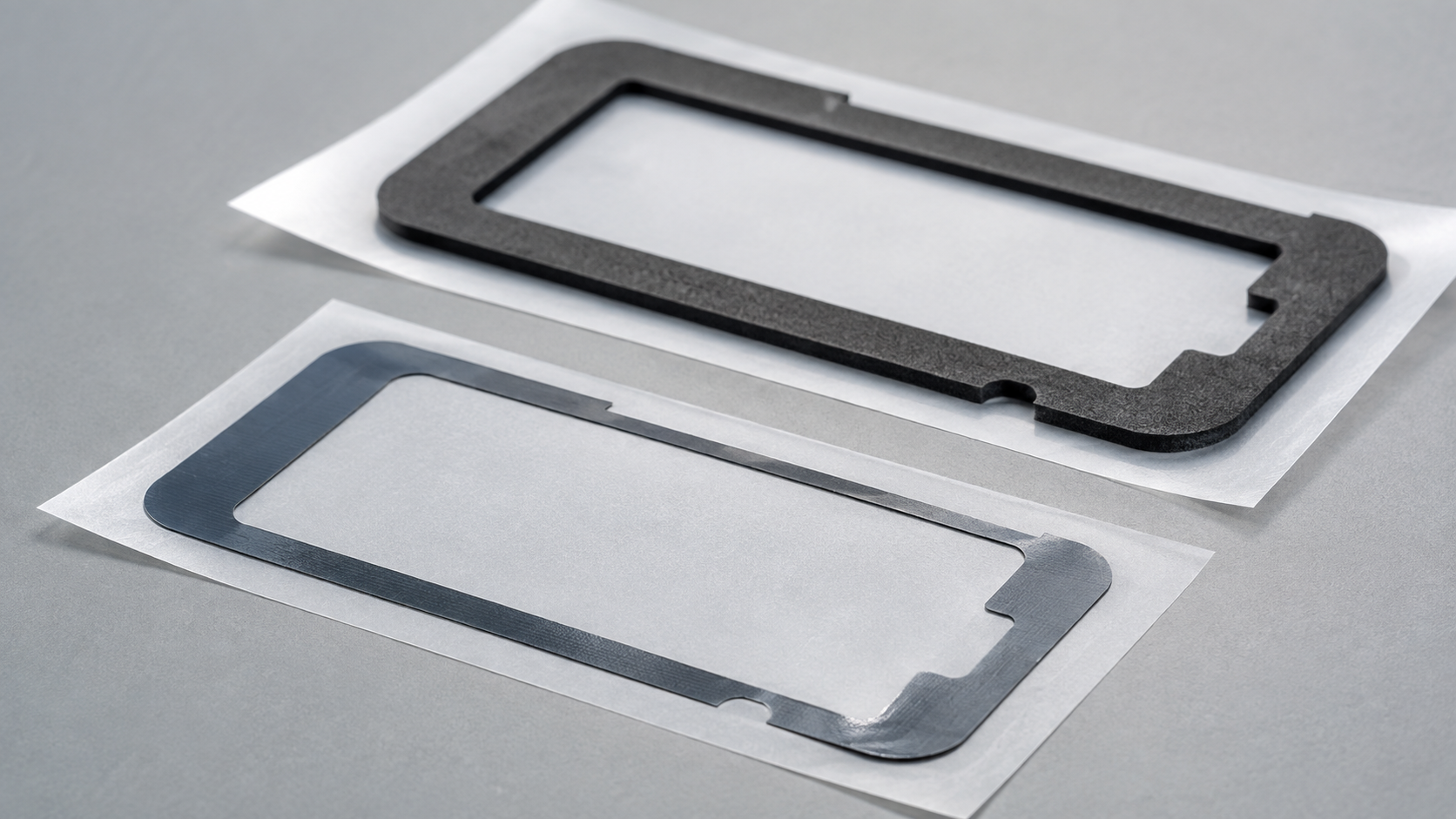
Die-Cutting Quality Affects Display Adhesive Performance
The purpose of die cutting is not only to create the correct outline. The process must also preserve the adhesive structure and make the part practical to assemble.
Important converting controls include:
Cut Depth
For kiss-cut parts, the tool should cut the adhesive component while keeping the release liner functional. An unstable cut depth may damage the liner or leave parts difficult to separate.
Edge Condition
Compressed, distorted or contaminated adhesive edges can affect narrow bonding areas. Tooling condition, material behavior and cutting method should be considered during sampling.
Adhesive Position
In laminated structures, the adhesive must remain within the intended profile. Misaligned layers may create exposed adhesive, weak areas or interference with nearby openings.
Waste Removal
Narrow frames and small internal cutouts require controlled waste removal. Excessive pulling force can stretch the part, damage corners or disturb its position on the liner.
Part Spacing
For roll-supplied parts, spacing and orientation affect peeling, indexing and placement. These details should be defined according to the customer’s manual or automated assembly method.
Sanken’s optical and display converting capabilities cover adhesive-backed films, protective films, PET films, light-blocking components and related precision die-cut parts for display and optical applications.
Liner and Pull-Tab Design Support Accurate Placement
A correctly cut adhesive frame can still fail during assembly if it is difficult to remove from the liner.
When liner release is too high, the operator may pull or twist the frame. Narrow borders can stretch, and one corner may touch the surface before the rest of the part is aligned. When the liner is too weak or unstable, it may curl or tear during handling.
The liner system should be reviewed for:
- Release force
- Liner stiffness
- Peeling direction
- Split-liner position
- Extended liner edges
- Pull-tab size and location
- Part orientation
- Manual or automated application
A pull tab or extended liner can reduce direct contact with the adhesive and make the starting point easier to control. However, its position must not deform a narrow section of the tape frame.
For additional design considerations, see How Pull Tabs Make Die Cut Adhesive Parts Easier to Apply.
Surface Preparation and Assembly Pressure Matter
Even a well-designed die-cut adhesive tape cannot compensate for an unsuitable bonding surface.
Before application, the customer should establish a controlled surface preparation method. The bonding area should be free from dust, oil, fibers, moisture and residues that interfere with adhesive contact.
Assembly pressure should also be applied across the complete tape path. If pressure is concentrated only at the center or on one edge, sections of the perimeter may not wet out correctly.
The assembly team should define:
- Surface cleaning procedure
- Time between cleaning and bonding
- Placement method
- Application pressure
- Bonding sequence
- Repositioning limitations
- Hold time before the next production step
- Inspection criteria after application
These parameters depend on the selected tape and assembly equipment. They should be confirmed during trials rather than copied from an unrelated application.
Packaging Can Prevent Lifting Before Assembly
Die-cut adhesive parts can be affected before they reach the production line. Curling, compression, dust exposure and poor stacking may change the condition of a thin frame.
Suitable supply formats may include:
- Kiss-cut parts on sheets
- Roll-form parts with controlled spacing
- Individual pieces with protective liners
- Assembly kits arranged by installation sequence
- Clean bags or trays where the application requires them
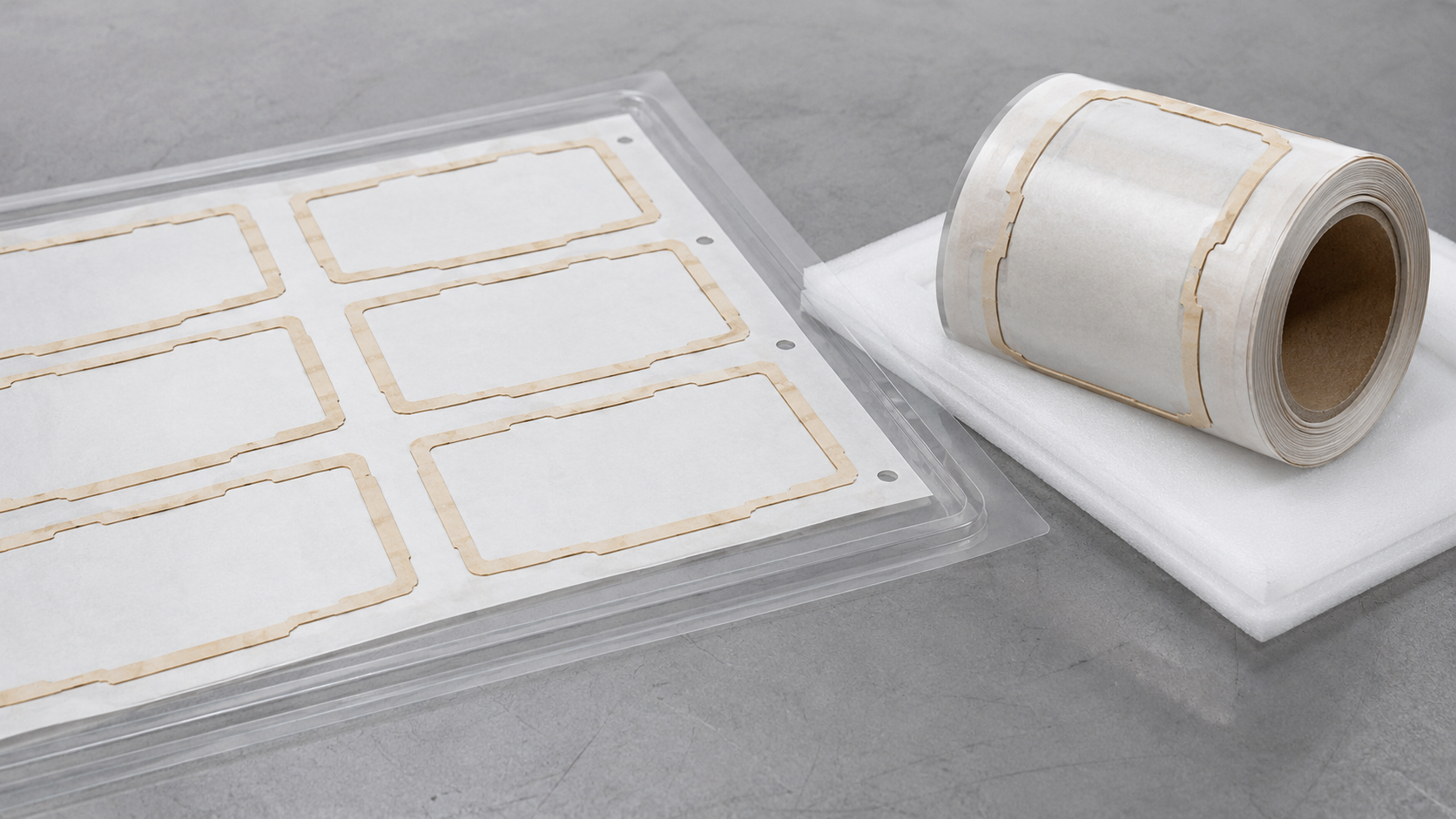
The best format depends on volume, operator movement, assembly equipment and part geometry. Roll supply may support continuous production, while sheet supply may be more practical for prototypes or manually assembled products.
Sanken’s adhesive tape converting process can include laminating, slitting, rewinding, kiss cutting, through cutting, waste removal and application-specific packaging.
What Should Be Checked Before Production?
Before approving a display adhesive tape component, engineers should review the complete relationship between the material, geometry and assembly process.
Key checks include:
- Inner and outer dimensions
- Bonding width at narrow sections
- Corner and opening geometry
- Tape structure and total thickness
- Compatibility with both bonding surfaces
- Liner release and peeling direction
- Part flatness and edge condition
- Adhesive exposure or overflow
- Supply orientation and packaging
- Assembly trials on actual production surfaces
Prototype parts should be evaluated using representative substrates and assembly conditions. Any required environmental or reliability testing should be defined by the customer according to the final application.
Conclusion
Die-cut adhesive tape can improve display module bonding by providing a controlled perimeter shape, consistent adhesive position and assembly-ready delivery format. Preventing edge lifting requires more than accurate cutting: the adhesive must match the bonding surfaces, the frame geometry must remain stable, the liner must peel cleanly, and the packaging must protect the part until use.
If you are evaluating a custom die-cut adhesive tape for a display application, send Sanken your drawing, bonding surfaces, material requirement, thickness, critical dimensions, annual volume and preferred delivery format. Our team can review the converting and manufacturing feasibility before sampling.
Related Articles
How to Avoid Edge Lift, Glue Overflow, and Adhesive Failure in Die-Cut Tape Parts
How Precision Die-Cutting Improves Adhesive Tape Assembly Accuracy
How to Choose Die-Cut Films and Adhesive Materials for Display Module Assembly
What Die-Cut Films and Adhesive Materials Are Used in Display Module Assembly?