
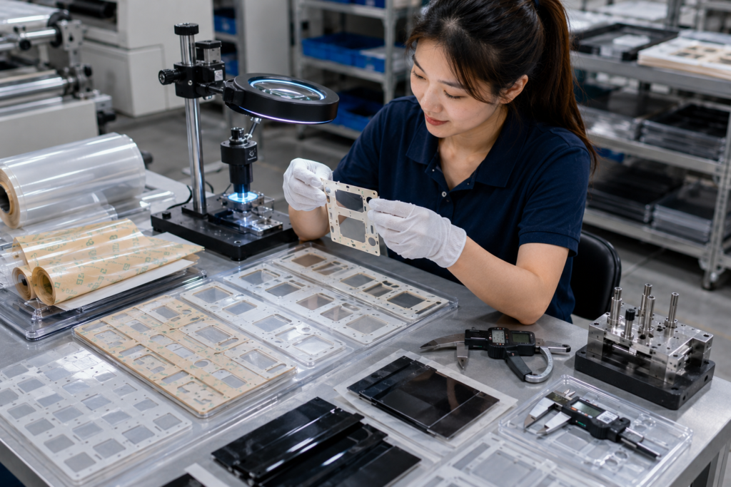
PET insulation film is widely used for thin electrical barriers, protective covers, adhesive-backed pads, frames, and custom insulation components. However, its relatively thin and stable structure can expose cutting problems that may be less noticeable in softer materials.
Burrs, size drift, cracked corners, rough edges, incomplete cuts, and distorted openings can affect fit, handling, insulation coverage, and downstream assembly. Preventing these defects requires control of material condition, tooling, cutting pressure, web tension, adhesive lamination, waste removal, and inspection throughout production.
PET Film Defects Often Begin Before the Cutting Step
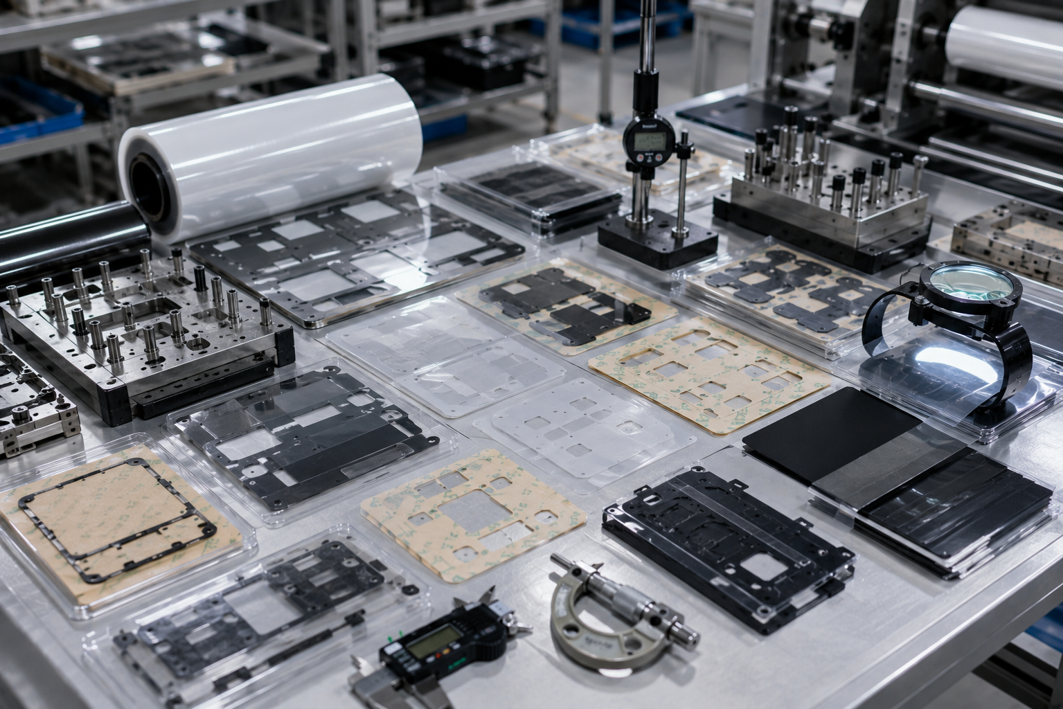
A visible edge defect may appear during die cutting, but its root cause can begin earlier in the converting process. Film storage, lamination, slitting, web tension, adhesive condition, and liner flatness can all influence the final cut.
PET film should be reviewed for:
- Thickness consistency
- Surface cleanliness
- Flatness
- Curl
- Residual stress
- Adhesive coating uniformity
- Liner compatibility
Material that has been stored under unsuitable temperature or humidity conditions may curl or move during cutting. A laminated structure may also shrink or distort if the adhesive, PET film, and liner behave differently under pressure or temperature.
Before production begins, the converter should confirm that the PET film lies flat, feeds consistently, and maintains stable dimensions through the complete process.
Burrs and Rough Edges Usually Point to Tooling Problems
A clean PET edge requires a sharp, stable cutting tool and the correct cutting method. A worn blade may crush or drag the film instead of separating it cleanly.
This can create:
- Raised burrs
- White stress marks
- Frayed or rough edges
- Partially cut areas
- Edge cracking
- Film delamination
| Defect | Common Cause | Recommended Action |
|---|---|---|
| Raised burr | Dull blade or excessive pressure | Sharpen or replace the tool and reset pressure |
| Rough edge | Poor blade geometry or unstable material | Review tooling angle and material support |
| White edge | Excessive stress during cutting | Reduce pressure and improve tool sharpness |
| Incomplete cut | Insufficient pressure or uneven die height | Rebalance the tool and verify cutting depth |
| Cracked corner | Sharp geometry or brittle material condition | Add corner radii and review material handling |
Tooling selection should consider film thickness, part geometry, adhesive construction, release-liner type, and production volume. A tool suitable for foam may not produce the same edge quality in thin PET film.
For high-volume programs, regular tool-maintenance intervals should be established before visible defects become widespread. The cutting tool should be inspected for wear, damage, contamination, and uneven blade height.
Cutting Pressure Must Be Controlled Across the Entire Tool
Excessive cutting pressure is a common response when incomplete cuts appear, but simply increasing pressure can create new problems.
Too much pressure may cause:
- Burr formation
- Liner damage
- Tool wear
- PET deformation
- Adhesive squeeze-out
- Distorted holes
- Uneven part dimensions
Too little pressure can leave uncut areas or make waste removal unstable.
The goal is not maximum force. It is the minimum stable pressure required to achieve a clean and repeatable cut.
Pressure should be checked across the full die area because a tool may cut correctly on one side but incompletely on the other. Machine parallelism, die height, backing condition, and material thickness can all influence pressure distribution.
When adhesive-backed PET is kiss cut, the blade should cut through the PET and adhesive without damaging the release liner. This requires tighter process control than simple through cutting.
Sanken’s precision die cutting services support kiss-cut and through-cut PET components in sheet and roll formats according to the customer’s assembly method.
Size Drift Can Result from Tension, Heat, and Material Movement
Size drift means that the finished part gradually moves away from the approved drawing dimensions during production. It may affect the outer profile, hole spacing, slot position, or registration between layers.
PET film is dimensionally stable compared with many soft materials, but the complete web structure can still move when tension, heat, pressure, or adhesive relaxation changes.
| Source of Size Drift | Effect on the Part |
|---|---|
| Excessive web tension | Lengthwise stretching or registration shift |
| Uneven tension | Skewed outlines and inconsistent hole position |
| Heat buildup | Temporary or permanent dimensional movement |
| Adhesive relaxation | Layer shift after lamination or cutting |
| Liner curl | Poor feeding and unstable positioning |
| Tool movement | Repeated offset or inconsistent registration |
| Waste pulling force | Distortion of narrow walls and small features |
Roll-to-roll production requires stable unwind, feed, cutting, and rewind tension. Sudden changes can alter registration or stretch the laminated structure.
Material should not be pulled through the cutting station by excessive tension. The web should be guided and supported so that cutting occurs on a stable, flat surface.
Measurements should also be taken after the part has relaxed. A component measured immediately under web tension may appear correct but change after removal from the liner.
Part Geometry Strongly Influences Edge Quality
PET insulation parts often contain narrow walls, small holes, internal corners, slots, and complex frames. These features can be difficult to cut and remove cleanly.
Sharp internal corners concentrate stress and are more likely to crack or whiten. Very narrow sections can stretch during matrix removal. Holes placed too close to an outer edge may distort or tear.
Better design practices include:
- Adding practical internal corner radii
- Maintaining sufficient material between holes and edges
- Avoiding unnecessarily narrow bridges
- Providing adequate spacing between parts
- Identifying only truly critical tolerances
- Reviewing adhesive setback around edges
A small design adjustment can significantly improve cutting stability without changing the part’s function.
For example, replacing a sharp 90-degree internal corner with a controlled radius can reduce stress, improve waste removal, and extend tool life. Increasing the width of a narrow PET bridge may prevent deformation when the surrounding waste matrix is removed.
The relationship between geometry and tolerance is especially important for parts that must align with connectors, fasteners, or electrical contact areas. The article on why tolerance control can make or break die cut components explains why critical dimensions should be separated from non-critical features.
Adhesive and Release Liners Can Affect the Cut
Adhesive-backed PET is a multilayer structure rather than a single film. The adhesive and release liner influence cutting depth, edge cleanliness, flatness, and waste removal.
An adhesive that is too soft may squeeze outward during cutting. This can leave sticky edges, collect dust, or cause neighboring parts to remain connected.
A release liner that is too thin or too soft may be easily damaged during kiss cutting. A liner that is too stiff or curled may create feeding and registration problems.
Important factors include:
| Layer | Key Process Concern |
|---|---|
| PET film | Edge quality, thickness, and dimensional stability |
| Adhesive | Squeeze-out, bonding strength, and temperature behavior |
| Release liner | Cutting resistance, flatness, and peel performance |
| Carrier film | Registration and support during processing |
| Laminated foam or rubber | Compression and layer alignment |
The converter should test the entire material stack, not only the PET film. A cutting setting that works for bare PET may fail after adhesive lamination.
Liner cutting depth should be checked repeatedly during production. Small changes in tool wear, material thickness, or pressure can turn a correct kiss cut into a liner-damaging cut.
Waste Removal Must Not Distort Narrow PET Features
After cutting, the surrounding waste matrix must be removed without pulling or deforming the finished parts.
PET components with narrow walls, small tabs, or closely spaced holes are particularly sensitive to waste-removal force. If the matrix is removed too quickly or at an unsuitable angle, parts may lift, stretch, tear, or shift on the liner.
Stable waste removal depends on:
- Tool sharpness
- Part spacing
- Matrix strength
- Peel angle
- Removal speed
- Adhesive tack
- Web tension
The waste matrix should separate cleanly from the finished parts. If waste repeatedly breaks, the process should be reviewed rather than relying on manual correction.
Part orientation on the roll can also influence waste removal. Rotating the layout or changing the spacing may reduce stress on weak features and improve production stability.
For adhesive-backed PET components, kiss-cut delivery can keep finished parts organized and protect the adhesive until installation. The format should be designed around the OEM’s production process, as explained in how die cut parts are supplied in sheets, rolls, or kits.
In-Process Inspection Prevents Defects from Reaching the Full Batch
Final inspection alone is not enough for long production runs. Burrs, pressure changes, tool wear, and size drift can develop gradually.
A practical control plan should include:
- First-piece inspection
- Scheduled dimensional checks
- Edge inspection under magnification
- Cutting-depth verification
- Registration checks
- Liner-damage inspection
- Adhesive-overflow inspection
- Tool-condition monitoring
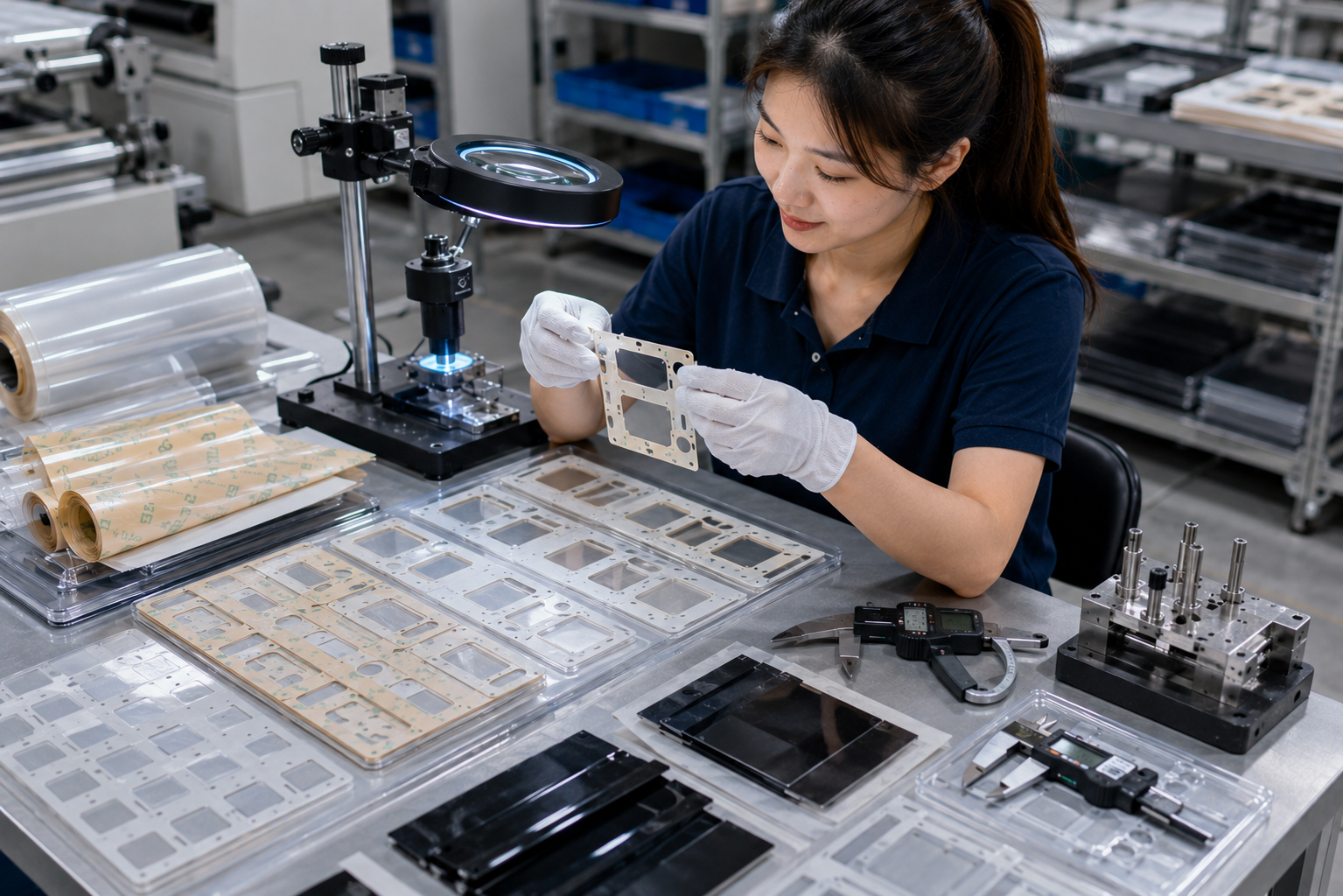
Critical dimensions should be measured using suitable gauges, optical inspection equipment, or calibrated measuring systems.
Edge quality should also be evaluated visually and functionally. A part may pass dimensional inspection but still contain a raised edge, stress crack, or partially separated feature.
Inspection frequency should reflect the production volume, tool life, material variation, and risk level of the application. High-risk dimensions and features should be checked more often than general outer edges.
How Sanken Controls PET Insulation Film Die Cutting
Sanken converts PET insulation films, adhesive-backed PET structures, protective films, and related flexible materials into custom die cut components. We support material review, laminating, slitting, kiss cutting, through cutting, roll-to-roll production, waste removal, and dimensional inspection.
Before mass production, we review the drawing, material stack, corner geometry, critical tolerances, cutting method, liner requirements, and delivery format. Process parameters are then controlled to reduce burrs, dimensional drift, edge damage, adhesive overflow, and liner-cutting defects.
You May Also Be Interested In
- Why Insulation Films Must Be Precision Die Cut for Electronics
- Why Tolerance Control Can Make or Break Die Cut Components
- What Makes Multi-Layer Die Cut Parts Difficult to Produce?
- Adhesive-Backed Die Cut Components for OEM Assembly
- How to Avoid Costly Mistakes in Custom Die Cut Parts
Conclusion
Burrs, size drift, and edge defects in PET insulation film die cutting are usually caused by a combination of tooling wear, incorrect pressure, unstable tension, unsuitable geometry, adhesive behavior, liner variation, or uncontrolled waste removal.
Reliable production depends on controlling the complete converting process rather than focusing only on the cutting blade. Material conditioning, sharp tooling, balanced pressure, stable web handling, practical part geometry, and regular in-process inspection all contribute to cleaner edges and more consistent dimensions.
Early drawing review and prototype validation allow engineers and converters to identify weak corners, narrow sections, unstable material stacks, and difficult liner structures before mass production. This reduces scrap, assembly problems, repeated adjustments, and the risk of defective insulation components reaching the final product.