
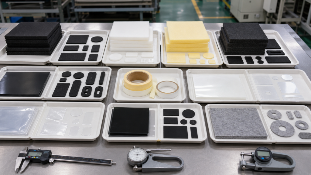
A custom die-cut component may appear simple on a drawing, but small decisions made during material selection, product design, sampling and packaging can significantly increase the final project cost.
Many expensive problems do not begin during mass production. They begin before tooling is prepared.
A foam gasket may tear because its walls are too narrow. An adhesive component may fail because the bonding surface was not reviewed. A PET film part may curl after the release liner is removed. A dimensionally correct sample may still fail during assembly.
These issues can lead to:
- Repeated sampling
- Tool modifications
- Material waste
- Low production yield
- Manual sorting
- Assembly delays
- Customer complaints
- Rework and replacement costs
At Sanken, we provide precision die cutting services for foam, rubber, adhesive tape, PET film, protective film, black light-blocking film and non-woven felt components.
The following nine mistakes are among the most common causes of unnecessary cost in custom die-cut OEM projects.
1. Selecting Materials Based Only on Price
Material cost is important, but the lowest-priced material does not always produce the lowest total manufacturing cost.
Materials with similar thicknesses can behave very differently during cutting, compression, bonding and long-term use.
For example:
- Soft foam may provide good contact against uneven surfaces but may stretch during waste removal.
- Dense foam may maintain its shape more effectively but may create excessive compression force.
- PET film may provide stable insulation or separation, but thin material may curl or shift if tension is not controlled.
- Rubber may provide sealing and cushioning, but hardness and compression recovery can affect assembly.
- Non-woven felt may reduce noise and protect contact surfaces, but loose fibers and edge cleanliness must be controlled.
- Soft adhesive may improve initial bonding but can create edge overflow during cutting.
Material selection should consider:
- Product function
- Thickness
- Density or hardness
- Compression recovery
- Temperature exposure
- Moisture resistance
- Bonding surface
- Adhesive compatibility
- Expected service life
- Cutting and waste-removal behavior
The most suitable material is one that meets the functional requirement while remaining stable during converting, assembly and use.
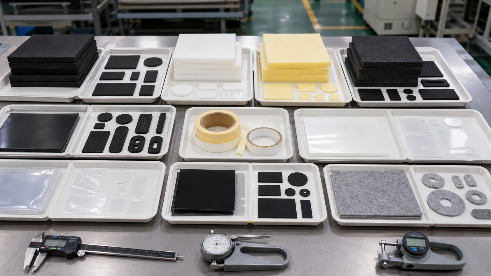
2. Applying Tight Tolerances to Every Dimension
Tight tolerances can increase tooling adjustments, inspection frequency and rejection rates.
However, not every dimension affects the final assembly in the same way.
A mounting hole may require close positional control. A non-functional outer edge may allow a wider tolerance without affecting performance.
Flexible and compressible materials also cannot always be evaluated using the same tolerance logic as machined metal parts.
Foam compresses under cutting pressure and may rebound after cutting. Soft adhesive may move along the edge. PET film may be affected by web tension, temperature and liner stress. Multilayer parts may include both cutting and lamination variation.
Before tooling, dimensions should be separated into different categories.
| Dimension Type | What Should Be Confirmed |
|---|---|
| Critical assembly dimension | Required fit, sealing or positioning tolerance |
| Hole or window position | Alignment with assembly features |
| Outer profile | Practical tolerance based on material behavior |
| Material thickness | Supplier specification and compression range |
| Layer alignment | Acceptable adhesive, foam or film exposure |
| Release liner position | Peeling and handling requirement |
| Reference dimension | Whether production inspection is necessary |
The goal is not to make every tolerance as tight as possible.
The goal is to control the dimensions that affect function while avoiding unnecessary production cost.
3. Designing Walls, Holes and Corners That Are Too Small
The geometry shown in a CAD drawing may be possible to draw but difficult to manufacture consistently.
Common design risks include:
- Narrow foam gasket walls
- Small holes near an outer edge
- Sharp internal corners
- Thin bridges between openings
- Long unsupported adhesive frames
- Closely spaced components
- Complex outlines with small details
These features may create problems during cutting, waste removal and customer handling.
| Design Feature | Possible Manufacturing Problem |
|---|---|
| Narrow foam wall | Stretching or tearing during waste removal |
| Sharp internal corner | Stress concentration and waste matrix breakage |
| Small hole near an edge | Hole distortion or edge tearing |
| Thin unsupported bridge | Deformation during peeling or handling |
| Long adhesive frame | Curling, lifting or difficult positioning |
| Tight part spacing | Weak waste matrix and unstable stripping |
Adding a practical corner radius can reduce stress concentration and improve manufacturing stability.
Minimum wall width, hole diameter and edge distance should be reviewed according to:
- Material type
- Material thickness
- Foam density
- Adhesive softness
- Cutting method
- Release liner support
- Waste-removal direction
- Expected production quantity
A custom die-cut component should be reviewed as a flexible material structure, not only as a two-dimensional outline.
4. Selecting Adhesive Without Reviewing the Bonding Surface
Adhesive should not be selected only according to thickness or initial tack.
Its performance depends on the actual assembly surface and operating environment.
Important factors include:
- Surface energy
- Surface texture
- Dust or oil contamination
- Assembly temperature
- Operating temperature
- Humidity
- Installation pressure
- Contact time
- Chemical exposure
- Long-term aging
Smooth metal, painted surfaces, textured plastics and rubber substrates may require different adhesive characteristics.
Adhesive failure may occur when:
- The assembly surface is contaminated.
- The bonding area is too narrow.
- The installation pressure is insufficient.
- The component is applied at a low temperature.
- The adhesive is unsuitable for the surface energy.
- Foam recovery continuously pulls against the adhesive bond.
For adhesive-backed foam gaskets and sealing components, the foam and adhesive should be evaluated together.
A foam with strong recovery force may create continuous stress on the adhesive. Even a high-strength adhesive can fail if the foam compression and bonding conditions are not properly matched.
5. Treating the Release Liner as Simple Packaging
The release liner is not only used to protect the adhesive.
It also determines how operators peel, handle, position and install the finished component.
Depending on the assembly process, the part may require:
- Extended release liners
- Split liners
- Finger-lift edges
- Pull tabs
- Liner replacement
- Multiple parts on one carrier
- Controlled spacing
- Defined winding direction
An unsuitable liner design may cause operators to:
- Touch the adhesive surface
- Bend thin film components
- Stretch narrow foam gaskets
- Install the part in the wrong direction
- Damage the edge during peeling
- Spend excessive time removing each part
The release liner should be confirmed before tooling.
For roll-form parts, buyers should also define:
- Leading edge
- Part orientation
- Winding direction
- Core diameter
- Part spacing
- Maximum roll diameter
- Quantity per roll
These requirements affect tooling, die-cutting layout, inspection and packaging.
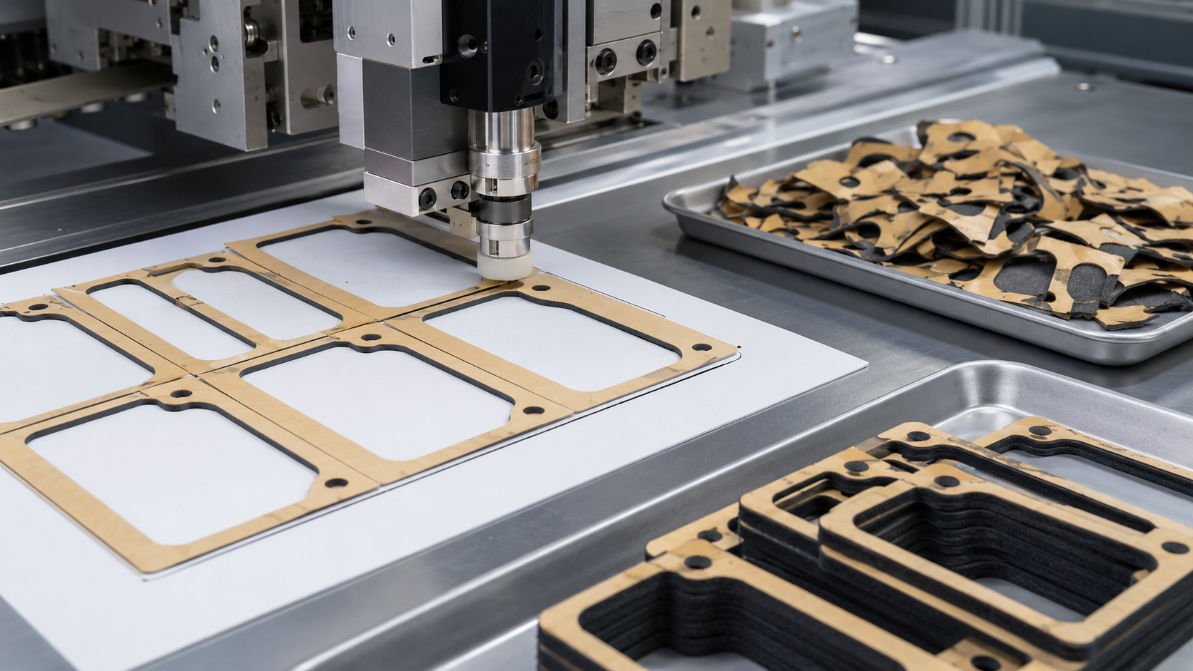
6. Ignoring Waste-Removal Stability
After the part is cut, the surrounding material must be removed without damaging the finished component.
This process is commonly called waste matrix removal or stripping.
Waste removal can become unstable when a part contains:
- Narrow gasket walls
- Sharp corners
- Small internal holes
- Soft foam
- Soft adhesive
- Thin unsupported sections
- Closely spaced components
Common waste-removal problems include:
- Finished parts lifting with the waste
- Internal holes remaining in the component
- Narrow foam sections stretching
- Waste material breaking repeatedly
- Adhesive sticking to nearby components
- Manual removal after machine processing
These problems may reduce production speed and increase labor cost.
The layout with the highest material utilization is not always the layout with the lowest total cost.
A slightly larger distance between components may use more material but improve waste-removal stability, production speed and finished-part consistency.
7. Approving Samples Without Testing the Actual Assembly
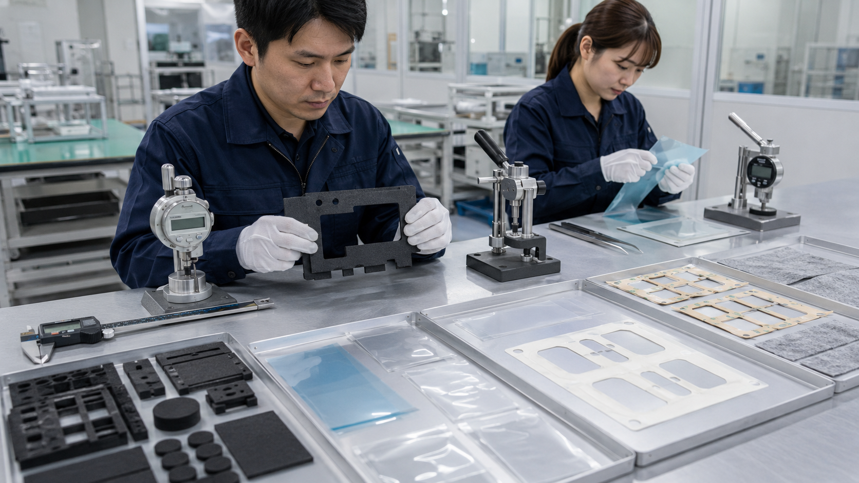
A sample can meet the drawing dimensions and still fail during installation or use.
Sample approval should include more than measuring the outer length, width and hole position.
Depending on the application, testing may include:
- Assembly fit
- Compression behavior
- Adhesive bonding
- Peel performance
- Release liner removal
- Hole alignment
- Surface cleanliness
- Installation direction
- Operator handling
- Packaging recovery
For example, a foam gasket may match the drawing but create excessive compression when installed.
A PET film component may meet dimensional requirements but curl after the release liner is removed.
An adhesive frame may bond well to a smooth test panel but fail on the customer’s actual textured plastic surface.
Where possible, samples should be evaluated using:
- The real assembly surface
- The actual installation method
- The expected compression gap
- The operating environment
- Representative packaging conditions
The customer should approve both the part and the installation process.
8. Maximizing Material Utilization at Any Cost
Improving material utilization can reduce raw material cost, particularly for expensive adhesive tape, foam or film materials.
However, placing components too close together may create additional production problems.
Possible consequences include:
- Weak waste matrix
- Repeated stripping breaks
- Adhesive contamination
- Reduced machine speed
- Unstable part spacing
- Increased manual sorting
- Higher rejection rates
The die-cutting layout must balance:
- Material utilization
- Cutting stability
- Waste removal
- Tooling structure
- Part orientation
- Roll direction
- Customer handling
- Packaging efficiency
The lowest material waste does not always produce the lowest total manufacturing cost.
A stable layout that uses slightly more material may still be more economical if it reduces production stoppages, manual work and rejected parts.
9. Choosing the Delivery Format Too Late
The delivery format affects the tooling layout, release liner, part spacing, inspection method and packaging design.
Custom die-cut parts may be supplied in:
- Rolls
- Sheets
- Individual pieces
- Trays
- Bags
- Assembly-ready kits
Roll Supply
Roll-form parts may be suitable for automated application or higher-volume manual installation.
The customer should confirm part orientation, winding direction, core size, spacing and quantity per roll.
Sheet Supply
Sheets keep several parts organized on one common liner.
This format may simplify counting, inspection, picking and manual assembly.
Individual Parts
Loose parts may be suitable for simple components or materials without adhesive backing.
Packaging must prevent bending, compression, contamination and deformation.
Assembly Kits
Several foam, tape, film, rubber or felt parts can be packed together when they are installed in the same assembly.
If the delivery format is selected after tooling has already been completed, the project may require:
- New liner structures
- Tool modifications
- Different part spacing
- Revised packaging
- Additional inspection
- More manual labor
The customer’s assembly process should therefore be reviewed before tooling begins.
Buyer Checklist Before Tooling
Before approving tooling, OEM buyers and engineers should confirm the following information.
| Evaluation Area | What to Confirm |
|---|---|
| Application | Sealing, cushioning, insulation, bonding, protection or noise reduction |
| Material | Type, thickness, density, hardness and performance requirement |
| Geometry | Minimum wall width, hole size, corner radius and edge distance |
| Tolerance | Critical and non-critical dimensions |
| Adhesive | Bonding surface, temperature and installation conditions |
| Release liner | Pull tab, split liner, extended liner or roll structure |
| Production | Quantity, cutting method and waste-removal stability |
| Validation | Dimensions, assembly fit, compression and peel performance |
| Delivery | Rolls, sheets, individual parts or kits |
| Packaging | Cleanliness, deformation protection and transportation requirements |
Providing this information before tooling can reduce repeated samples, unexpected changes and production delays.
How Sanken Supports Custom Die-Cut Projects
At Sanken, we help OEM customers reduce custom die-cut part risks before tooling and mass production.
We review material selection, adhesive structure, tolerance requirements, release liner design, waste-removal stability, inspection points and delivery format based on the customer’s real assembly process.
Our core converting support includes adhesive lamination, precision die cutting, kiss cutting, waste matrix removal, dimensional inspection and customized packaging for foam, rubber, PET film, adhesive tape, protective film, black light-blocking film and non-woven felt components.
For automotive applications, our automotive die-cut components include custom foam, rubber, adhesive tape, PET film and non-woven parts used for sealing, cushioning, bonding, surface protection and anti-rattle control.
Conclusion
Most costly custom die-cut part mistakes begin before mass production. Wrong material selection, unrealistic tolerances, weak adhesive matching, unstable waste removal or late packaging decisions can all lead to repeated sampling, low yield and assembly problems.
A successful project should review the complete part structure before tooling, including material, geometry, adhesive, release liner, cutting process, inspection method, packaging and customer assembly.
Need help with a custom die-cut component?
Send us your drawing, sample, material requirement, tolerance, adhesive structure, application environment and expected quantity. Sanken can help review the project before tooling and mass production.
Related Articles
- How to Choose the Right Die Cutting Manufacturer for Your OEM Project
- How to Select Precision Die Cutting Components
- From Foam Rolls to Finished Parts: How Die Cutting Works
- How Die-Cut Parts Are Supplied in Sheets, Rolls or Kits
- What Is Die Cut? Definition, Meaning and Applications
- Where Are Die-Cut Parts Used in Automotive Manufacturing?