
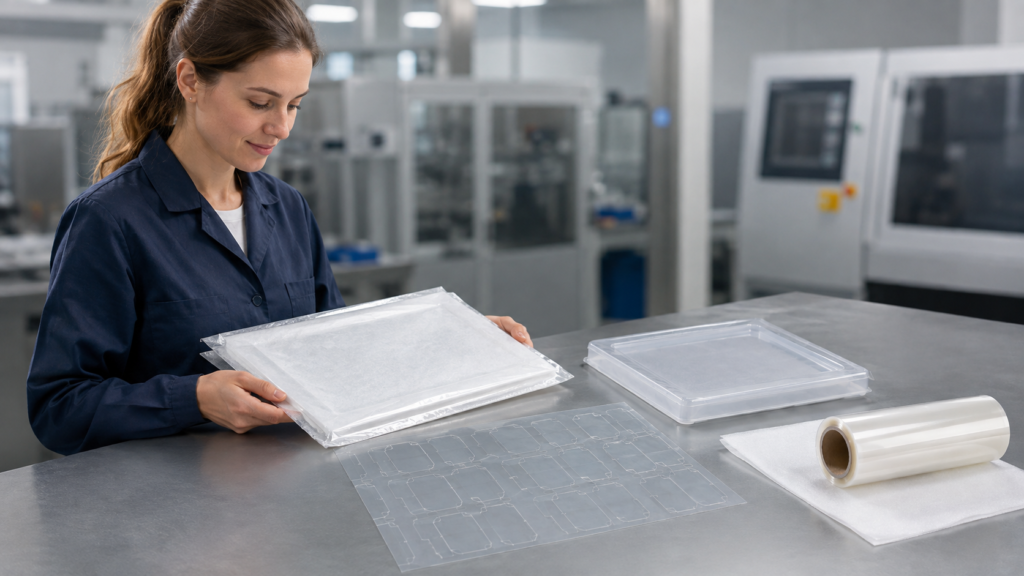
Optical protective film helps reduce scratches by creating a temporary barrier between sensitive surfaces and the contact, particles, fixtures and repeated handling involved in assembly. However, the film must fit the protected area, remain stable during production and remove without contaminating or marking the surface. Die-cut geometry, adhesive behavior, liner design, application timing and packaging all affect the result. This article explains how OEM engineers can control these factors when protecting lenses, display surfaces, sensor windows and other precision optical components.
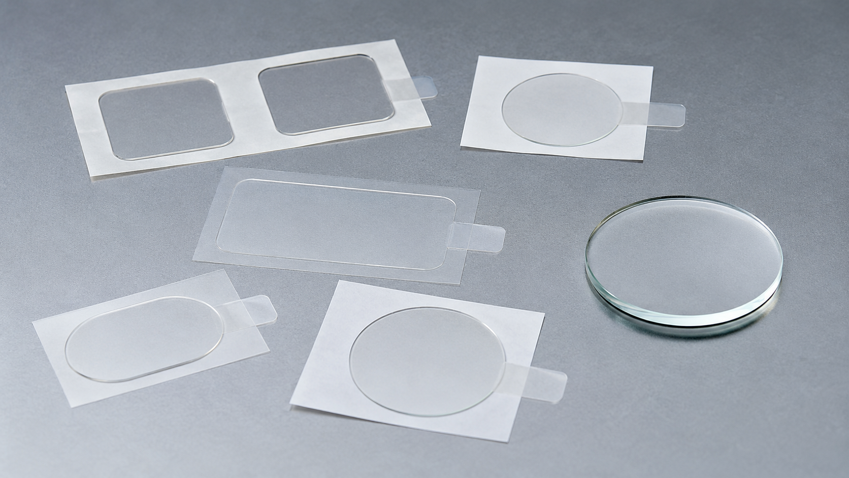
Why Optical Surfaces Get Scratched During Assembly
An optical surface may pass through inspection, fixture loading, bonding, testing, cleaning, temporary storage and packaging before the final product is completed. Damage can occur at any of these stages.
Common causes include:
- Sliding components across a work surface
- Dust or hard particles trapped between stacked parts
- Contact with fixtures, trays or packaging
- Repeated picking and repositioning
- Exposed edges not covered by the film
- Film movement caused by insufficient adhesion
- Scratches introduced during liner removal
- Poor stacking or transportation control
A scratch does not need to be deep to create a problem. On a lens cover, display window or coated optical surface, even a small visible mark may lead to appearance rejection or additional cleaning and rework.
Protective film should therefore be considered part of the assembly process rather than an accessory added after damage occurs.
Accurate Die-Cut Coverage Protects Critical Areas
Roll material can cover a large surface, but OEM components often contain windows, holes, curved borders and areas that must remain accessible. Custom precision die cutting converts the film into a shape that matches the actual protection requirement.
The drawing should identify:
- The surface that requires protection
- Areas that must remain uncovered
- Critical optical windows
- Outer-edge clearance
- Hole and slot positions
- Reference edges for placement
- Pull-tab location
- Film removal direction
If the film is too small, vulnerable edges remain exposed. If it is too large, it may interfere with assembly features or create lifting at unsupported sections.
Accurate geometry also reduces the need for operators to trim protective film manually. Manual trimming may work during early sampling, but it introduces variation and additional surface-handling risk in production.
Sanken’s optical and display component capabilities include custom protective films, PET films, adhesive tape parts and black PET light-blocking films for precision OEM applications.
The Protected Surface Determines the Film Requirement
The same protective film may behave differently on glass, coated glass, transparent plastic or a treated optical surface. Surface energy, texture, coating condition, storage time and removal timing can all influence adhesion and clean removal.
The film must stay in place during the required process without becoming difficult to remove. Two opposite problems can occur:
| Film behavior | Assembly risk |
|---|---|
| Adhesion is too low | Film shifts, lifts or exposes the protected surface |
| Adhesion is too high | Removal becomes difficult or may leave residue |
| Film is too flexible | Wrinkles and stretching complicate placement |
| Film is too stiff | Edges may lift around complex geometry |
| Poor surface compatibility | Marks, bubbles or unstable adhesion may occur |
| Incorrect removal timing | Adhesion may change after extended storage |
Material and adhesive performance should be tested on the actual surface whenever possible. A visual sample on an unrelated substrate cannot confirm performance on the production component.
For broader selection considerations, review how to choose die-cut protective films for electronics and display modules.
Liner and Pull-Tab Design Reduce Handling Damage
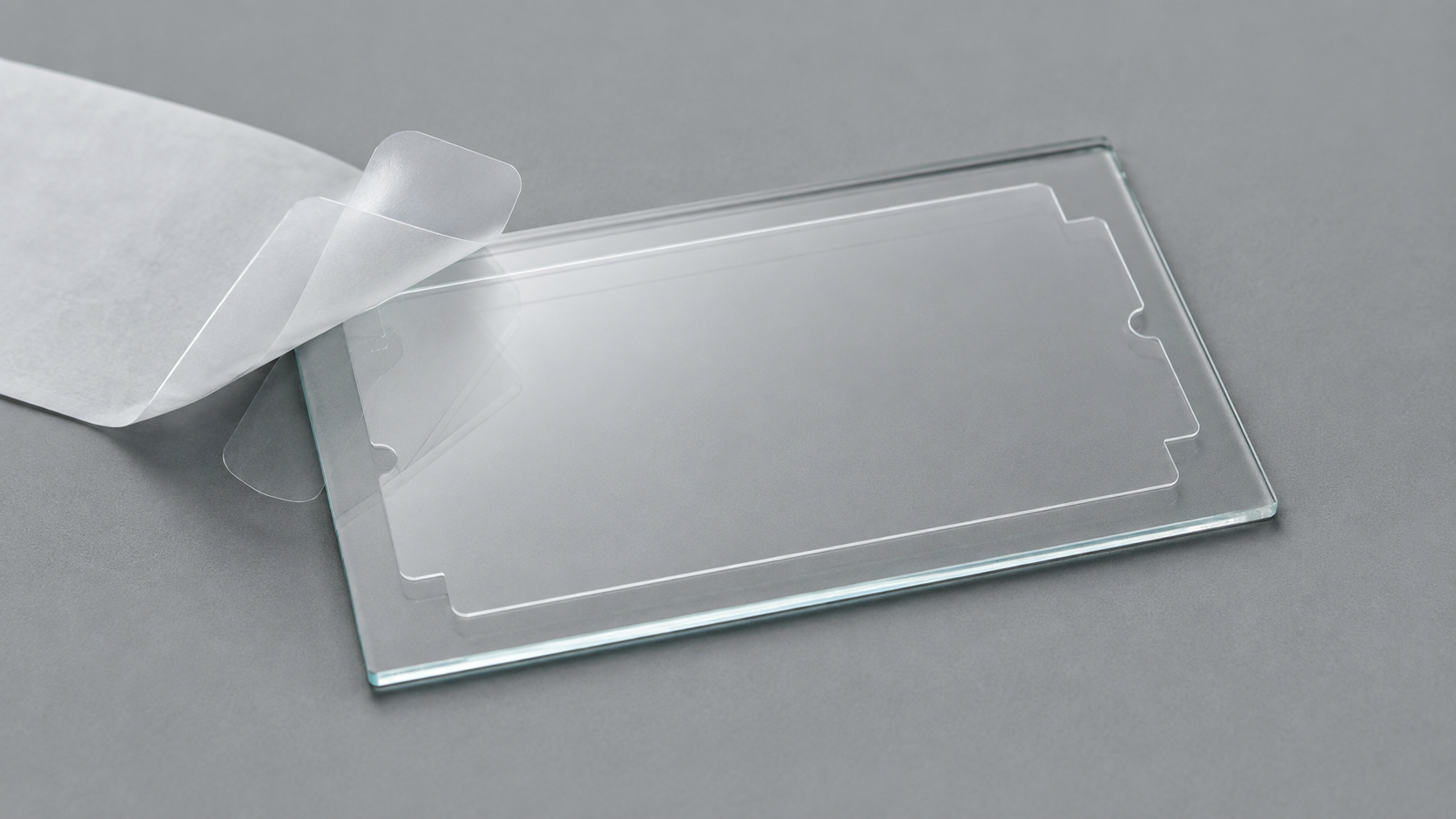
A thin film may stretch, fold or attract contamination when it is difficult to remove from its liner. Operators may also touch the adhesive surface or protected area while trying to separate the layers.
A suitable liner structure can help the part remain flat before application. Depending on the assembly method, the design may include:
- Kiss-cut parts on a common liner
- Extended liner sections
- Split liners
- Pull tabs
- Defined part orientation
- Controlled part spacing
- Sheet or roll presentation
Pull tabs give operators a non-functional area to grip during application or final removal. Their position should match the planned peel direction and available assembly space.
Kiss cutting can keep the protective film supported until placement. Cutting depth must separate the film cleanly without weakening or cutting through the liner. Poor depth control may create difficult peeling, torn liner material or unstable part release.
Apply the Film Before High-Risk Handling Begins
A correctly designed protective film cannot prevent damage that occurs before it is applied. The production team should determine when the surface first becomes vulnerable.
Application may be required before:
- Fixture loading
- Repeated inspection
- Transfer between workstations
- Temporary stacking
- Secondary assembly
- Transportation
- Final packaging
The surface should be suitable for film application at that point. Applying film over dust or particles can trap hard contamination against the optical surface. Pressure applied during stacking or assembly may then turn the trapped particle into a scratch source.
Application timing, surface condition and operator method should be validated together.
Packaging Must Protect Both the Film and the Component
A protective film can itself become scratched, curled or displaced when finished parts are packed incorrectly. If the film shifts during transportation, the optical surface may become partially exposed.
Packaging should reduce:
- Film-to-film rubbing
- Edge lifting
- Dust entry
- Part movement
- Excessive stacking pressure
- Curling or bending
- Pull-tab damage
- Adhesive contamination
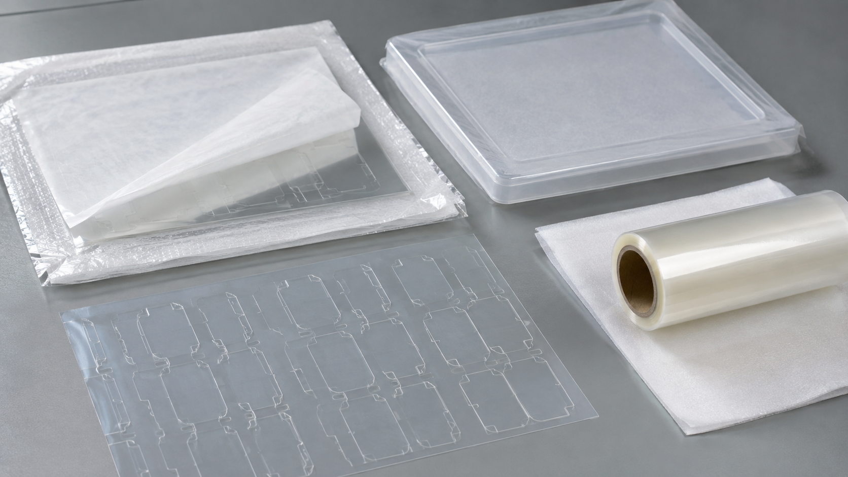
Parts may be supplied on sheets, rolls or project-specific liners according to the assembly process. The guide to sheet, roll and kit supply formats explains how presentation affects handling and production use.
For continuous placement, roll-to-roll die cutting may support consistent part orientation and spacing. Sheet supply may be more practical for manual placement, multiple shapes or smaller production batches.
Inspection Should Cover More Than Dimensions
Dimensional inspection confirms whether the film matches the drawing, but scratch prevention also depends on surface condition and handling performance.
Relevant inspection points may include:
- Outer dimensions
- Window and hole positions
- Edge condition
- Film flatness
- Visible scratches or particles
- Adhesive overflow
- Liner condition
- Pull-tab geometry
- Part orientation
- Packaging condition
The acceptance criteria must come from the customer’s drawing, sample or quality requirements. Sanken should not assume a numerical scratch limit, cleanliness level or dimensional tolerance without project-specific information.
How Sanken Supports Optical Protective Film Projects
Sanken converts protective films into custom shapes with windows, holes, pull tabs and liner-backed structures. Available processing support includes laminating, slitting, rewinding, kiss cutting, through cutting, waste removal, inspection and packaging.
Our team can review the protected surface, drawing, film structure, application sequence, liner design and preferred delivery format before sampling. The related article on how PET protective film parts are made for OEM assembly provides additional manufacturing context.
If you are evaluating an optical protective film project, send Sanken your drawing, protected surface, film requirement, thickness, removal timing, annual volume and preferred sheet or roll format. We can review the converting and assembly feasibility before sample production.
Conclusion
Optical protective film reduces scratch risk only when the complete protection process is controlled. Accurate die-cut coverage protects critical areas, compatible adhesion keeps the film stable, liner and pull-tab design reduce handling contact, and suitable packaging prevents movement and contamination. Testing these factors on the actual optical surface before production helps identify lifting, residue, peeling and handling problems before they affect assembly quality.
Related Articles
- How to Choose Die-Cut Protective Films for Electronics and Display Modules
- PET Protective Film Die Cutting: How Custom Film Parts Are Made for OEM Assembly
- When Do OEM Products Need Custom Die-Cut Surface Protection Films?
- Roll-to-Roll Die Cutting for Adhesive Tape, Foam and Protective Film Components
- How Die-Cut Parts Can Be Supplied in Sheets, Rolls or Kits
- Black PET Film vs Protective Film: What Is the Difference for OEM Applications?