
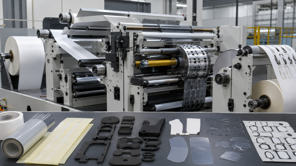
A rotary die cutting machine uses cylindrical cutting tools to continuously convert roll-fed materials into precise custom components. It can cut, kiss cut, laminate, slit, remove waste and rewind materials in one controlled production process.
For OEM engineers and purchasing teams, however, the machine itself is only part of the solution.
The quality of a finished die-cut component also depends on material selection, cutting depth, web tension, adhesive behavior, liner condition, waste removal and dimensional stability.
At Sanken, we provide precision die cutting services and material converting for custom OEM components. We use rotary die cutting equipment to process foam, adhesive tape, PET film, protective film, rubber and non-woven materials into parts supplied in rolls, sheets or assembly-ready kits.
We do not sell rotary die cutting machines. Our role is to help customers turn drawings, material specifications and assembly requirements into consistent production parts.
What Is a Rotary Die Cutting Machine?
A rotary die cutting machine is a continuous converting system that feeds flexible materials between rotating cylinders.
One cylinder holds the cutting tool, while another cylinder provides support beneath the material. As the material moves through the machine, the rotating die cuts the required shape repeatedly.
Depending on the tooling and machine setup, rotary die cutting can perform several operations:
- Through cutting
- Kiss cutting
- Perforating
- Slitting
- Laminating
- Liner replacement
- Waste matrix removal
- Part spacing control
- Rewinding
- Sheet cutting
Because the material moves continuously, rotary die cutting is especially suitable for medium- and high-volume production where repeatability, speed and organized part presentation are important.
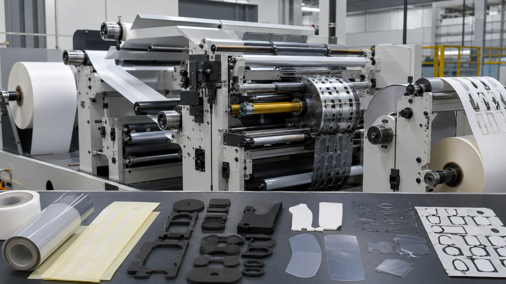
Main Stations of a Rotary Die Cutting Machine
A rotary die cutting line may contain several stations. The exact configuration depends on the material structure and the final component design.
Material Unwinding
The process begins with one or more rolls of raw material.
These rolls may include:
- Foam
- Double-sided adhesive tape
- Transfer adhesive
- PET film
- Protective film
- Rubber sheet
- Non-woven felt
- Release liner
Stable unwinding is important because uneven feeding can cause wrinkles, stretching and registration errors.
Web Guiding and Tension Control
The material must remain correctly aligned as it moves through the machine.
Web guiding systems control lateral movement, while tension systems help prevent the material from becoming too loose or too tight.
Incorrect tension may cause:
- PET film stretching
- Foam deformation
- Liner wrinkles
- Poor layer alignment
- Inconsistent part spacing
- Dimensional variation
Thin films and soft foam materials often require different tension settings.
Laminating
Some components consist of multiple layers.
For example, a foam gasket may require adhesive on one side. A PET film component may need a release liner or adhesive backing. A protective film may require a pull tab or extended liner.
The laminating station combines these layers before or between cutting operations.
Sanken processes multilayer structures such as:
- Foam with double-sided adhesive
- Rubber with adhesive backing
- PET film with pressure-sensitive adhesive
- Non-woven felt with adhesive
- Protective film with pull tabs
- Foam, film and adhesive combinations
For adhesive-backed foam, PET film or rubber parts, buyers can also review adhesive-backed die cut components to understand liner release, kiss cutting and adhesive overflow risks.
Rotary Cutting Station
The rotary cutting station contains the die cylinder and support cylinder.
The cutting tool must penetrate the required material layers without damaging layers that need to remain intact.
For example, during kiss cutting, the die may cut through:
- Foam
- Adhesive
- PET carrier film
while leaving the release liner uncut.
This requires careful control of tool height, machine pressure and material thickness.
Waste Matrix Removal
After cutting, the unwanted material around the finished parts must be removed.
This process is known as waste matrix removal or stripping.
Waste removal becomes more difficult when a component has:
- Narrow walls
- Small internal holes
- Sharp corners
- Soft adhesive
- Thin unsupported sections
- Closely spaced parts
Good component geometry and appropriate part spacing can reduce waste breakage and improve production stability.
Rewinding or Sheet Cutting
Finished parts can be supplied in different formats.
Die-cut parts supplied in sheets are often suitable for manual assembly, inspection and kitting.
Roll-form parts are often selected for:
- Automated assembly
- Continuous production lines
- Label-style dispensing
- Controlled part orientation
- High-volume operator use
Individual parts or kits may be appropriate when several components are installed together during assembly.
How Does the Rotary Die Cutting Process Work?
A typical rotary die cutting process follows these steps.
1. Review the Drawing and Application
Before production, we review the customer’s drawing and assembly requirements.
Important details include:
- Outer dimensions
- Internal holes and windows
- Material thickness
- Adhesive side
- Release liner structure
- Part orientation
- Roll or sheet direction
- Pull-tab requirements
- Packaging format
A part that looks simple in CAD may behave differently when produced from compressible foam, flexible film or soft adhesive.
2. Confirm the Material Structure
The complete layer structure must be defined before tooling is prepared.
For example:
| Component | Possible Structure | Typical Purpose |
|---|---|---|
| Foam gasket | Foam + adhesive + release liner | Sealing, cushioning or spacing |
| PET film part | PET film + adhesive + liner | Electrical insulation or separation |
| Protective film | Transparent film + pull tab | Temporary surface protection |
| Rubber pad | Rubber + adhesive | Sealing, anti-slip or cushioning |
| Non-woven felt part | Felt + adhesive | Noise reduction or surface protection |
| Adhesive frame | Double-sided tape + liner | Component bonding and positioning |
Material thickness variation must also be considered because it can affect cutting depth and finished dimensions.
3. Prepare the Tooling
Rotary tooling is produced according to the approved drawing.
Tool design must consider:
- Corner radius
- Hole size
- Cutting sequence
- Material compression
- Waste removal direction
- Part spacing
- Tool life
- Liner protection
Sharp internal or external corners may increase the risk of tearing, lifting or waste matrix failure. A practical corner radius can often improve both part performance and production yield.
4. Set Up Lamination and Cutting
The selected materials are loaded into the machine and aligned.
Machine settings are adjusted for:
- Web tension
- Cutting pressure
- Registration
- Lamination pressure
- Line speed
- Waste removal
- Rewinding tension
Initial samples are inspected before mass production begins.
5. Inspect the Finished Parts
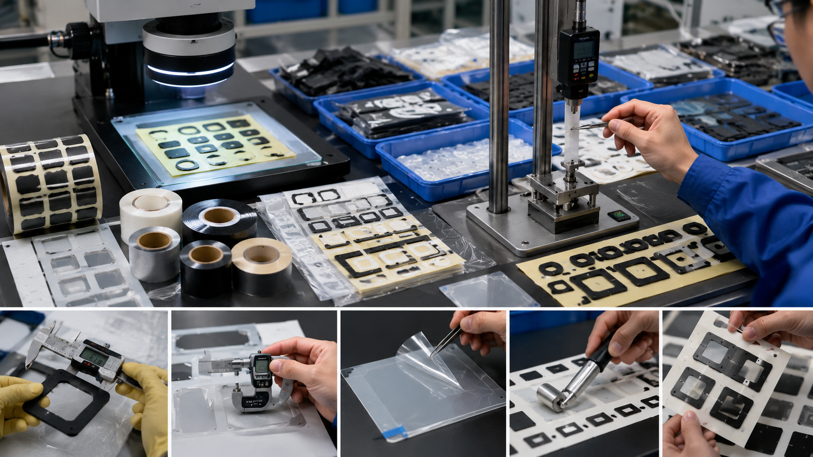
Inspection may include:
- Outer dimensions
- Hole and window position
- Layer alignment
- Kiss-cut depth
- Release liner condition
- Adhesive overflow
- Edge cleanliness
- Surface scratches
- Curling
- Part spacing
- Peel and release performance
The correct inspection method depends on the material and the customer’s application.
What Materials Can Sanken Process?
Sanken uses rotary and other die cutting processes for materials that are clearly within our converting capabilities.
Foam Materials
Foam is commonly converted into:
- Adhesive-backed foam gaskets
- Cushioning pads
- Spacers
- Sealing strips
- Anti-vibration pads
We process materials such as EVA, PE, PU and EPDM foam according to project requirements.
Because foam is compressible, cutting pressure and dimensional inspection must account for temporary deformation.
Adhesive Tapes
Adhesive materials may be converted into:
- Double-sided tape frames
- Transfer adhesive components
- PET-backed adhesive parts
- Foam tape gaskets
- Bonding pads
- Positioning strips
Release liner design is important because it affects how the customer peels, handles and installs the part.
Options may include split liners, extended liners and pull tabs.
PET Films
PET film can be converted into:
- Electrical insulation parts
- Separation films
- Protective film components
- Adhesive-backed PET parts
- Thin spacers
- Die-cut film frames
Thin PET film requires stable web tension to reduce stretching, curling and registration variation.
Protective and Light-Blocking Films
Sanken can process:
- Transparent protective films
- Protective films with pull tabs
- Black light-blocking film frames
- Adhesive-backed film components
- Custom windows and openings
Surface cleanliness is particularly important because scratches, dust and fingerprints may make otherwise dimensionally correct parts unusable.
Rubber and Non-Woven Materials
Rubber can be converted into adhesive-backed pads, seals and cushioning parts.
Non-woven felt can be converted into:
- Noise-reduction pads
- Surface protection parts
- Anti-rattle strips
- Adhesive-backed felt components
- Custom felt shapes
For projects involving foam gaskets and sealing components, material hardness, thickness and compression behavior should be reviewed together.
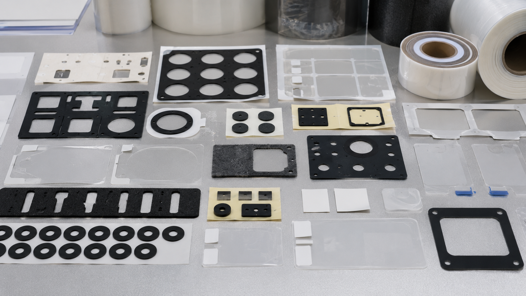
Rotary Die Cutting vs Flatbed Die Cutting
Rotary and flatbed die cutting are both valuable manufacturing methods. The better option depends on the component design, material and production volume.
Rotary Die Cutting Is Often Suitable When:
- The material is supplied in rolls
- Production volume is medium or high
- Parts need consistent spacing
- Kiss cutting is required
- Finished parts need to remain on a liner
- Roll-form delivery is required
- Lamination and cutting need to be integrated
Flatbed Die Cutting May Be Better When:
- Materials are thick or rigid
- Production quantities are lower
- Parts are large
- Tooling changes are frequent
- The material is supplied in sheets
- Prototypes or early-stage samples are needed
A project does not need to remain on one process throughout its life.
Flatbed die cutting may be used for samples and low-volume production, while rotary die cutting may be introduced after the design and demand become stable.
Common Rotary Die Cutting Problems
Rotary die cutting can be efficient, but poor material or process control may create defects.
Incomplete Cutting
If cutting pressure is too low, parts may not separate cleanly.
This can result in tearing during peeling or difficulty removing the waste matrix.
Damaged Release Liner
If the cutting depth is too great, the tool may cut into or through the release liner.
A damaged liner can break during rewinding, storage or customer assembly.
Adhesive Overflow
Soft adhesive may move under pressure and appear along the part edge.
Adhesive overflow can contaminate tools, cause parts to stick together and interfere with assembly.
Poor Waste Removal
Thin walls, sharp corners and small holes can remain attached to the waste material.
This may reduce production speed and increase manual inspection.
Layer Misalignment
Multilayer components may shift if tension, guiding or lamination pressure is not controlled correctly.
Layer misalignment can affect bonding area, exposed edges and hole position.
Curling
Thin films and asymmetrical adhesive structures may curl after cutting or liner removal.
Material selection, roll direction and liner design should be reviewed before production.
Design Details That Improve Production
Several small design decisions can make rotary die-cut parts easier to manufacture and assemble.
Use Practical Corner Radii
Rounded corners can reduce tearing, stress concentration and waste matrix breakage.
Allow Enough Space Between Parts
Very tight spacing may save material, but it can also weaken the waste matrix and make stripping unstable.
Consider the Peeling Direction
The liner should support the way operators or automated equipment remove the part.
Add Pull Tabs Where Necessary
Pull tabs can make thin protective films and adhesive parts easier to peel without touching the functional surface.
Confirm Roll Direction
For roll-form parts, the customer should confirm:
- Leading edge
- Winding direction
- Number of parts per roll
- Core size
- Maximum roll diameter
- Part orientation
These details should be agreed upon before mass production.
What Should Buyers Provide for a Rotary Die Cutting Project?
To evaluate a new project efficiently, customers should provide as much of the following information as possible:
- 2D drawing
- Material name or performance requirement
- Material thickness
- Adhesive requirement
- Release liner requirement
- Expected quantity
- Dimensional tolerance
- Sample availability
- Application environment
- Roll, sheet or individual-part preference
- Packaging and cleanliness requirements
When the final material has not yet been selected, we can review the application and discuss practical converting considerations.
For automotive projects, our automotive die-cut component capabilities include custom foam, rubber, film, adhesive tape and non-woven parts for sealing, cushioning, insulation, bonding and noise reduction applications.
Conclusion
A rotary die cutting machine is more than a high-speed cutting system. It is a coordinated converting process involving material feeding, tension control, lamination, precision cutting, waste removal, inspection and final part presentation.
For OEM customers, successful production depends on more than choosing a machine.
The material structure, adhesive, liner, geometry, tolerances, roll direction and assembly method must all work together.
At Sanken, we convert foam, adhesive tape, PET film, protective film, rubber and non-woven materials into custom OEM components using rotary and other precision die cutting processes.
Send us your drawing, material information and expected production format to discuss a practical converting solution for your project.
Related Articles
- Understanding Rotary Die Cutting: Process, Advantages, Materials and Applications
- Which Is Better: Rotary or Flatbed Die Cutting?
- How Die-Cut Parts Are Supplied in Sheets, Rolls or Kits
- From Foam Rolls to Finished Parts: How Die Cutting Works
- How to Choose the Right Die Cutting Manufacturer for Your OEM Project