
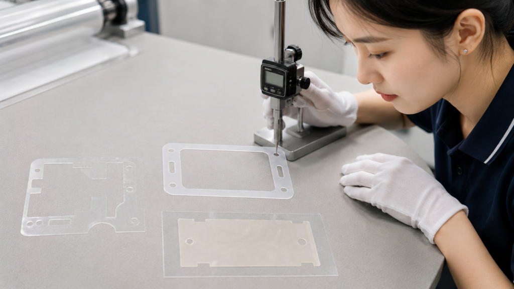
Custom die-cut PET insulation films are used to separate, cover and protect electrical areas inside compact electronic assemblies. Although these components are often thin and visually simple, their dimensions, edge quality, adhesive structure and placement accuracy can directly affect assembly reliability.
A PET insulation part that is too small may leave part of the required area exposed. A part that is too large may interfere with connectors, housings or adjacent components. Curling, particles, adhesive overflow and inaccurate openings can also create production problems.
For this reason, PET film selection and converting should be reviewed as one complete system. The insulation area, film thickness, adhesive, release liner, part geometry, tolerances and delivery format must all match the final assembly process.
Sanken provides precision die cutting services for PET insulation films, adhesive-backed PET parts, protective films and other thin converted materials used in OEM electronics assembly.
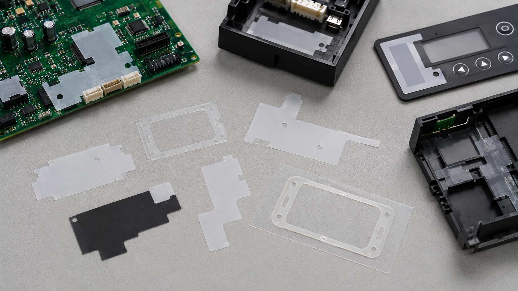
What Is a Custom Die-Cut PET Insulation Film?
PET, or polyethylene terephthalate, is a polyester film commonly used for electrical separation, surface protection and dimensional support.
Instead of using PET only in roll or sheet form, manufacturers can convert it into application-specific components with:
- Outer profiles
- Holes and slots
- Windows and openings
- Positioning tabs
- Narrow insulation frames
- Adhesive backing
- Release liners
- Pull tabs
- Multilayer laminated structures
These features allow the insulation part to fit around connectors, screw positions, component openings and housing features.
PET film is often selected because it combines thin construction, dimensional stability and practical converting performance. However, the exact material grade must be confirmed against the required electrical, thermal, environmental and regulatory conditions.
For a broader explanation of the material, see Why Is PET Film Commonly Used in Electronics?.
Start With the Required Insulation Area
Material selection should begin with the area that must be electrically separated or physically protected.
Engineers should confirm:
- Which surface requires insulation
- Which conductive areas must remain covered
- Which openings must remain clear
- Whether the part is used on a flat or curved surface
- Whether the PET film must wrap around an edge
- Whether the part must fit between other components
- Whether adhesive is permitted across the complete surface
- How the operator or equipment will position the part
The insulation boundary should not be determined only from the nominal drawing. Housing tolerances, connector movement, component position and placement variation may change the practical coverage required.
At the same time, adding unnecessary coverage can cause interference during assembly. The correct design balances insulation coverage with available space and realistic positioning tolerance.
Select PET Film Thickness According to the Assembly
PET film thickness affects more than electrical separation. It can also affect flexibility, flatness, handling, edge conformity and the total stack height of the assembly.
A thinner film may be suitable when:
- Assembly space is limited
- The part must conform to a surface
- Low added thickness is important
- The insulation shape is relatively simple
A thicker film may provide:
- Greater stiffness during handling
- Improved resistance to folding or wrinkling
- More physical separation
- Easier manual placement for some geometries
However, thicker does not automatically mean better. A thicker PET part may be more difficult to bend around an edge or fit inside a restricted gap.
The correct thickness should be confirmed from the product drawing, available space, insulation requirement and application method. More information is available in How to Choose PET Insulation Film Thickness for Electrical Applications.
When Should PET Film Have Adhesive Backing?
Plain PET film can work when the part is mechanically retained between components. Adhesive backing is useful when the insulation part must remain in a defined position during assembly or service.
Common structures include:
| Structure | Typical purpose |
|---|---|
| PET film without adhesive | Mechanically retained insulation or separation |
| Full-surface adhesive-backed PET | Permanent positioning on a compatible surface |
| Pattern-coated or partially laminated adhesive | Bonding while keeping selected areas free of adhesive |
| PET with release liner | Protection and handling before application |
| Kiss-cut PET parts on a common liner | Faster peeling and repeated assembly |
| PET with a pull tab | Easier liner removal during installation |
The adhesive must be compatible with the actual bonding surface. Smooth metal, coated metal, glass, ABS, PC and textured plastics may require different adhesive properties.
Important factors include:
- Surface material and finish
- Surface cleanliness
- Application temperature
- Operating temperature
- Required permanent or removable bonding
- Exposure to humidity or chemicals
- Assembly pressure
- Expected stress after installation
The adhesive should also be reviewed after die cutting. Soft adhesive may move toward the cut edge, creating adhesive bleed or difficult waste removal. For more information, see Adhesive-Laminated PET Film: Uses, Risks and OEM Die Cutting Tips.
Design Geometry and Tolerances Around Function
Not every dimension on a PET insulation part requires the same level of control.
Critical dimensions may include:
- The position of an opening relative to a locating feature
- The distance between an insulation edge and a conductive area
- The width of a narrow insulation wall
- The outside profile that fits inside a housing
- The position of an adhesive-free zone
- The relationship between multiple holes
- The alignment between laminated layers
A drawing should distinguish critical dimensions from general dimensions. Applying unnecessarily tight tolerances to every feature can increase tooling difficulty, inspection time and production cost without improving the final assembly.
Narrow walls and small openings require particular attention. If a wall is too narrow for the material thickness and cutting process, it may stretch, curl or remain attached to the waste matrix.
The drawing should also identify the measurement datum. If the supplier and customer measure from different reference points, both inspection results may appear correct while the part still does not fit the assembly.
Kiss Cutting, Release Liners and Waste Removal
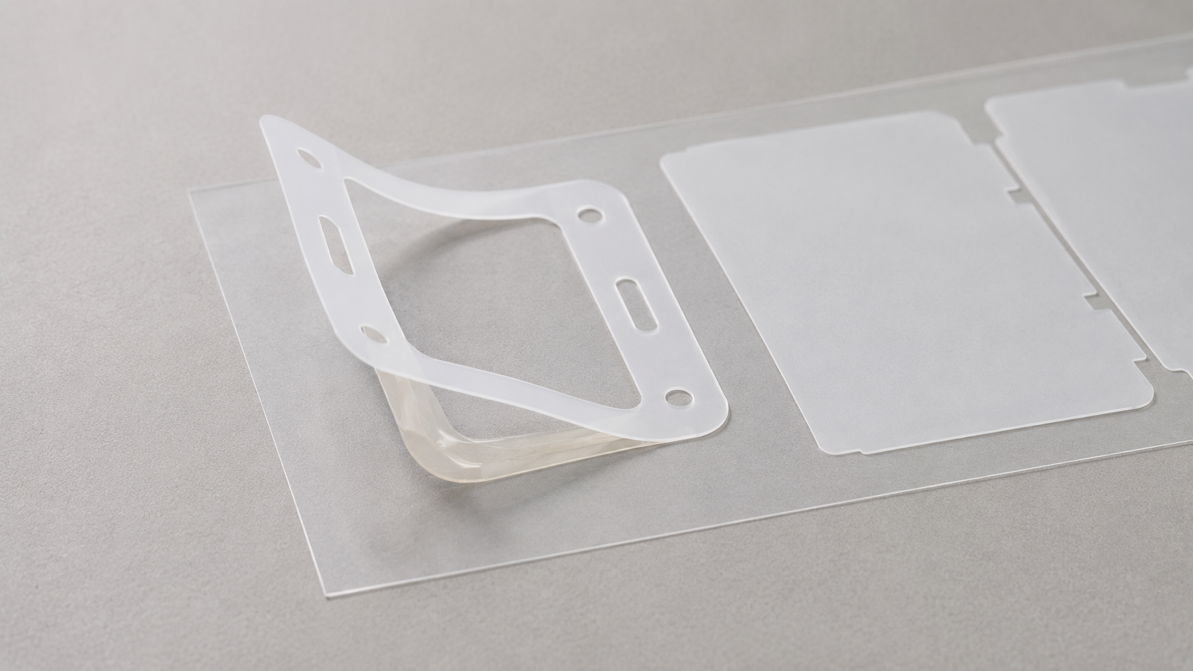
Adhesive-backed PET parts are often kiss cut so that each component remains on a release liner.
During kiss cutting, the tool cuts through the PET and adhesive layers without cutting through the liner. This makes the parts easier to store, transport, peel and position.
Cutting depth must be controlled carefully:
- A shallow cut may leave parts connected to the surrounding material.
- An excessive cut may weaken or penetrate the liner.
- Inconsistent depth may cause variable peeling during assembly.
- Adhesive accumulation on the tool may affect edge quality.
The release liner is not only packaging. Its release force, stiffness, thickness and surface condition influence converting and application.
Waste-matrix removal must also be considered during design. Closely spaced parts, narrow frames and small internal sections can make waste removal less stable. Part orientation and spacing on the liner may need to be adjusted to support clean stripping.
Common PET Film Problems and Their Causes
| Problem | Possible cause | Recommended review |
|---|---|---|
| Burrs or rough edges | Tool wear, unsuitable clearance or unstable material support | Tool condition and cutting method |
| Size drift | Material tension, temperature variation or tooling movement | Process stability and measurement method |
| Curling | Film stress, uneven lamination or packaging pressure | Material flatness and lamination conditions |
| Adhesive overflow | Soft adhesive or excessive cutting pressure | Adhesive grade and cutting parameters |
| Misaligned openings | Incorrect datum or layer-registration error | Drawing reference and lamination control |
| Difficult liner peeling | Unsuitable liner release or excessive die penetration | Liner selection and kiss-cut depth |
| Scratches or particles | Poor handling, waste removal or packaging | Cleanliness and contact surfaces |
| Part deformation | Narrow geometry or aggressive waste stripping | Wall width, spacing and stripping direction |
The defect should be connected to its actual process cause before changing the material. For a more detailed review, see How to Avoid Burrs, Size Drift and Edge Defects in PET Insulation Film Die Cutting.
Inspection and Validation Before Mass Production
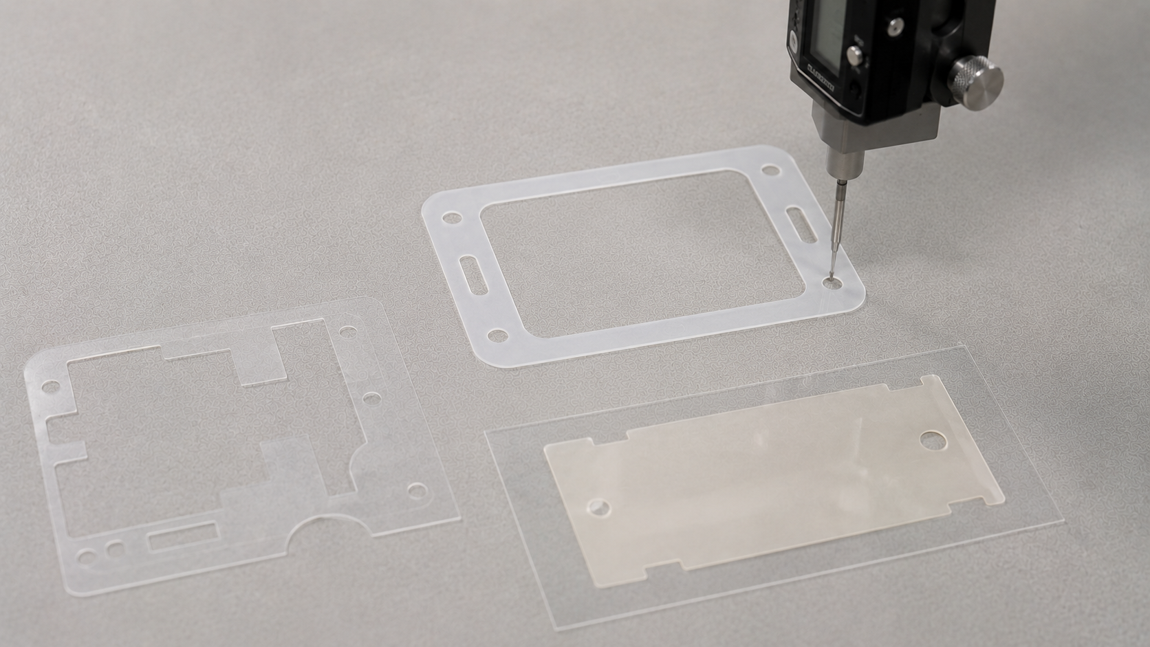
PET insulation parts should be inspected according to their functional risks, not only their outside dimensions.
A practical inspection plan may include:
- Material grade and thickness
- Outside dimensions
- Hole and window position
- Narrow-wall width
- Layer registration
- Cut-edge condition
- Surface cleanliness
- Adhesive position
- Liner integrity
- Liner release performance
- Part flatness
- Packaging condition
Prototype samples should be tested in the representative assembly whenever possible. A dimensionally acceptable part may still be difficult to peel, position or bond.
Validation should confirm:
- The PET film covers the required insulation area.
- Openings align with the relevant assembly features.
- The part does not interfere with nearby components.
- Adhesive-backed parts remain in position.
- The liner can be removed without deforming the film.
- The converted part tolerates the intended assembly process.
- Packaging protects the parts from curling, scratches and contamination.
Choose the Correct Delivery Format
The delivery format affects assembly efficiency and part protection.
| Delivery format | Suitable situation |
|---|---|
| Individual parts | Larger or lower-volume components |
| Parts in sheets | Manual assembly and grouped handling |
| Kiss-cut parts on rolls | Repetitive assembly or automated feeding |
| Parts on liner strips | Controlled manual peeling and positioning |
| Assembly kits | Several converted components used at one station |
For thin PET components, packaging should prevent bending, curling, scratching and particle contamination.
The part orientation, pitch, liner width and winding direction should be confirmed when roll delivery is required. Assembly teams should not assume these details can be decided after tooling.
See Die-Cut Parts in Sheets, Rolls, or Kits: How to Choose the Right Format for additional delivery considerations.
What Information Should Buyers Provide?
To evaluate a custom die-cut PET insulation film, buyers should provide:
- Two-dimensional drawing
- Three-dimensional assembly information when relevant
- PET material grade or required performance
- Required film thickness
- Color or appearance requirement
- First and second bonding surfaces
- Adhesive requirement
- Critical dimensions and tolerances
- Insulation coverage area
- Required liner type
- Peeling or placement method
- Sheet, roll, strip or individual delivery format
- Expected annual quantity
- Sample-validation requirements
- Packaging and cleanliness requirements
If the PET or adhesive grade has already been approved, it should be identified clearly. If it has not been selected, the application conditions should be provided so that candidate structures can be reviewed.
How Sanken Supports Custom PET Insulation Parts
Sanken converts customer-specified PET films, adhesives and release liners into custom components for electronics assembly.
Our processing support includes:
- Material lamination
- Precision die cutting
- Kiss cutting
- Slitting and rewinding
- Waste-matrix removal
- Multilayer registration
- Prototype sampling
- Dimensional inspection
- Sheet, roll and liner-supported delivery
Before production, we review the drawing, material structure, critical dimensions, liner configuration, part orientation and assembly method. This helps connect the converted part design with the customer’s actual production requirements.
Related Articles
- Why Is PET Film Commonly Used in Electronics?
- Adhesive-Laminated PET Film: Uses, Risks and OEM Die Cutting Tips
- How to Choose PET Insulation Film Thickness for Electrical Applications
- How to Avoid Burrs, Size Drift and Edge Defects in PET Insulation Film Die Cutting
- Die-Cut Parts in Sheets, Rolls, or Kits: How to Choose the Right Format
Conclusion
Custom die-cut PET insulation films should be designed around the actual insulation area, available assembly space, required film thickness, adhesive structure, tolerances and installation method.
Material selection alone does not guarantee a reliable part. Cutting quality, layer alignment, liner release, waste removal, cleanliness and delivery format also affect production performance.
By validating the complete converted structure under representative assembly conditions, OEM teams can reduce positioning problems, exposed insulation areas, edge defects, adhesive issues and handling delays before mass production.